
A null modem cable connects two DTE devices directly — two PCs, a PC and a controller console port, two pieces of test gear — with no modem in between. The whole job lives in the wiring. Transmit on one end has to reach receive on the other, and depending on the device, a few control lines have to cross too. Get the pinout wrong and you get silence, or a port that sits there waiting for a signal that never arrives.
This page gives you every pinout you’ll actually wire, for DB9 and DB25, plus a quick way to tell a null modem cable from a straight one.
Table of Contents
Start with one question
RS-232 was built to link a DTE to a DCE. A PC is a DTE. A modem is a DCE. In that pairing, straight pin-for-pin wiring works, because the modem already expects transmit and receive on the opposite pins from the PC.
The current version of the standard is TIA/EIA-232-F, which lines up with ITU-T V.24 (the signal definitions), ITU-T V.28 (the electrical side), and ISO/IEC 2110 (the connector). It grew out of the older RS-232-C, then EIA-232-D, then TIA/EIA-232-E. The F revision brought no technical changes that break compatibility with gear built to the earlier ones, so “RS-232” in the field almost always means the same interface.
Wire two DTE devices with a straight cable and both drive transmit onto the same conductor. Nothing gets through. A null modem cable solves this by crossing the signals, so each device’s transmit lands on the other device’s receive.
Keep one thing in mind: TIA/EIA-232-F and V.24 define the interface between a DTE and a DCE. They don’t define a “null modem” cable as such. The null modem is the technique the industry settled on for joining two DTEs, and because it’s a convention rather than one fixed wiring, you’ll see a few versions in the wild.
How many wires you cross comes down to one thing: does either device use hardware flow control?
- No flow control, or software flow control (XON/XOFF): three wires do the job.
- Hardware flow control (RTS/CTS): you also need the control lines wired.
Answer that before you cut anything. Every pinout below follows from it.
The signals and where they live
Before the crossing patterns make sense, here’s what each pin carries. Direction is written from the DTE’s point of view.
DB9 (DE-9), the standard PC serial port
| Pin | Signal | Name | Direction (DTE) |
|---|---|---|---|
| 1 | DCD | Data Carrier Detect | In |
| 2 | RXD | Received Data | In |
| 3 | TXD | Transmitted Data | Out |
| 4 | DTR | Data Terminal Ready | Out |
| 5 | GND | Signal Ground | — |
| 6 | DSR | Data Set Ready | In |
| 7 | RTS | Request To Send | Out |
| 8 | CTS | Clear To Send | In |
| 9 | RI | Ring Indicator | In |
DB25, the original RS-232 connector
| Pin | Signal | Name | Direction (DTE) |
|---|---|---|---|
| 2 | TXD | Transmitted Data | Out |
| 3 | RXD | Received Data | In |
| 4 | RTS | Request To Send | Out |
| 5 | CTS | Clear To Send | In |
| 6 | DSR | Data Set Ready | In |
| 7 | GND | Signal Ground | — |
| 8 | DCD | Data Carrier Detect | In |
| 20 | DTR | Data Terminal Ready | Out |
| 22 | RI | Ring Indicator | In |
Note the pin numbers move around between the two connectors. TXD is pin 3 on a DB9 but pin 2 on a DB25. That swap is the source of a lot of wiring mistakes, so keep both tables handy when you mix connector types.
RI (Ring Indicator) is almost never wired in a null modem cable. Two DTE devices don’t ring each other. Leave it open.
The short signal names come from RS-232 usage. Under ITU-T V.24 the same lines carry circuit numbers, and you’ll run into both on datasheets and in older documentation. Here’s the map:
| RS-232 name | V.24 circuit | V.24 name |
|---|---|---|
| TXD | 103 | Transmitted data |
| RXD | 104 | Received data |
| RTS | 105 | Request to send |
| CTS | 106 | Ready for sending |
| DSR | 107 | Data set ready |
| DTR | 108/2 | Data terminal ready |
| DCD | 109 | Data channel received line signal detector |
| RI | 125 | Calling indicator |
| GND | 102 | Signal ground / common return |
Two names worth flagging: V.24 calls CTS “ready for sending,” and it calls DCD “data channel received line signal detector.” Same lines, longer labels. The crossing rules below don’t change either way.
Need the pin-by-pin detail first? This page treats the DB9 pinout as a reference for wiring null modem cables. If you want the full breakdown of each DB9 signal — what it does, how it’s wired in a normal DTE-to-DCE link, and how to chase down a dead port in the field — start with RS-232 DB9 Pinout: Signal Reference, Wiring, and Field Troubleshooting, then come back here for the crossover wiring.
Type 1 — Three-wire null modem (no handshaking)
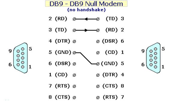
The simplest version. You cross transmit and receive, tie the grounds, and stop there. Use it when the link runs with no flow control or with software flow control (XON/XOFF), because XON/XOFF rides on the data lines and needs no separate wires.
DB9 to DB9
| End A | Signal | ↔ | End B | Signal |
|---|---|---|---|---|
| 2 | RXD | ← | 3 | TXD |
| 3 | TXD | → | 2 | RXD |
| 5 | GND | — | 5 | GND |
That’s the entire cable. Most console cables for switches, routers, and controller CPUs are wired exactly this way.
Type 2 — Loopback handshaking null modem
Some devices refuse to talk unless they see their handshake inputs go active. If you don’t want to run real handshake wires all the way across, you fool each device locally. On each connector, you loop the control outputs straight back into the control inputs on that same side.
You still only run three wires between the two ends. The handshake lines are tied together inside each connector shell.
DB9 to DB9
Wires that cross the cable:
| End A | Signal | ↔ | End B | Signal |
|---|---|---|---|---|
| 2 | RXD | ← | 3 | TXD |
| 3 | TXD | → | 2 | RXD |
| 5 | GND | — | 5 | GND |
Loopbacks, done inside each connector on both ends:
| Tie together (each side) | Signals |
|---|---|
| 7 + 8 | RTS to CTS |
| 1 + 4 + 6 | DCD to DTR to DSR |
Now each device raises RTS and immediately sees its own CTS. It raises DTR and sees its own DSR and DCD. Every device thinks the far end is always ready. Data still only flows on the three real wires, with no genuine flow control between the two devices. So use this only when the far side never actually needs to throttle the data.
This is the DB9 null modem shown in the TIA/EIA-232-F reference material, where RTS is fed straight back to CTS on each interface. It’s common because it satisfies devices that check their handshake inputs, without the extra conductors of a fully crossed cable.
Type 3 — Full handshaking null modem
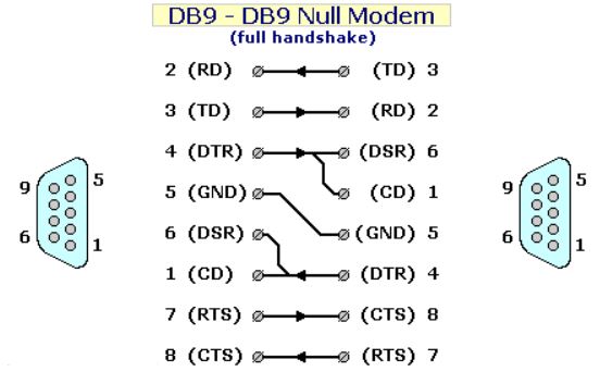
The complete cable. Instead of looping the handshake lines back locally, every control line crosses to its matching partner on the other end, so hardware flow control works for real. RTS on one side drives CTS on the other. DTR drives DSR and DCD together. This is what you want when either device relies on RTS/CTS to pace the traffic. Both this and the loopback version get called “null modem” cables, so when a datasheet says one is required, check which behavior it means.
DB9 to DB9
| End A | Signal | ↔ | End B | Signal |
|---|---|---|---|---|
| 3 | TXD | → | 2 | RXD |
| 2 | RXD | ← | 3 | TXD |
| 5 | GND | — | 5 | GND |
| 7 | RTS | → | 8 | CTS |
| 8 | CTS | ← | 7 | RTS |
| 4 | DTR | → | 6 + 1 | DSR + DCD |
| 6 + 1 | DSR + DCD | ← | 4 | DTR |
The DTR line is the one people miss. It doesn’t cross to a single pin. It feeds both DSR and DCD on the far end, so the other device sees the connection as “up” and “ready” at the same time.
Mixed connectors: DB9 to DB25
When one end is a DB9 and the other a DB25, the crossing logic is identical — you just land on different pin numbers. Here’s the full handshaking version.
| DB9 End | Signal | ↔ | DB25 End | Signal |
|---|---|---|---|---|
| 3 | TXD | → | 3 | RXD |
| 2 | RXD | ← | 2 | TXD |
| 5 | GND | — | 7 | GND |
| 7 | RTS | → | 5 | CTS |
| 8 | CTS | ← | 4 | RTS |
| 4 | DTR | → | 6 + 8 | DSR + DCD |
| 6 + 1 | DSR + DCD | ← | 20 | DTR |
Watch the ground: DB9 pin 5 goes to DB25 pin 7, not pin 5. And DTR on the DB25 side is pin 20, off on its own away from the rest.
DB25 to DB25
No handshaking (3-wire)
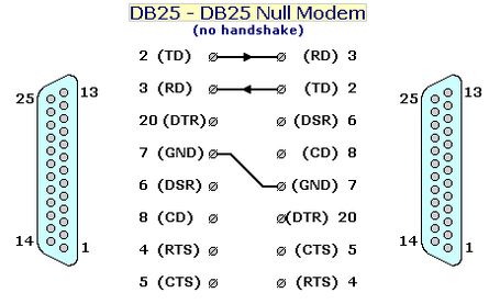
Same idea as the DB9 three-wire cable, just on the 25-pin connector. Cross transmit and receive, tie the grounds, leave everything else open. Use it with no flow control or software flow control (XON/XOFF).
| End A | Signal | ↔ | End B | Signal |
|---|---|---|---|---|
| 2 | TXD | → | 3 | RXD |
| 3 | RXD | ← | 2 | TXD |
| 7 | GND | — | 7 | GND |
Three conductors and you’re done. Note the ground is pin 7 on a DB25, not pin 5 like the DB9 — the single most common slip when someone moves from one connector to the other.
Full handshaking
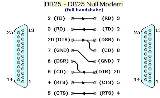
All control lines crossed, for devices that use RTS/CTS.
| End A | Signal | ↔ | End B | Signal |
|---|---|---|---|---|
| 2 | TXD | → | 3 | RXD |
| 3 | RXD | ← | 2 | TXD |
| 7 | GND | — | 7 | GND |
| 4 | RTS | → | 5 | CTS |
| 5 | CTS | ← | 4 | RTS |
| 20 | DTR | → | 6 + 8 | DSR + DCD |
| 6 + 8 | DSR + DCD | ← | 20 | DTR |
Gender, and the null modem adapter
The standard sets the convention: the DTE side carries male pins, the DCE side female. So a PC serial port (a DTE) is a male DB9. To reach two of them, a null modem cable needs a female connector on each end. Most off-the-shelf null modem cables are female-to-female for exactly that reason.
If you already have a straight-through serial cable, you don’t have to rewire it. A null modem adapter — a short shell with a male end and a female end — does the crossing for you. Plug it onto one end of a straight cable and the pair behaves as a null modem link. Handy for a field kit, since one adapter turns any straight cable into a crossover.
Null modem vs straight-through cable
Same connectors, completely different wiring. Mixing them up is the most common serial failure there is.
| Straight-through | Null modem | |
|---|---|---|
| Connects | DTE to DCE (PC to modem) | DTE to DTE (PC to PC / device) |
| TXD and RXD | Pin to same pin | Crossed |
| Control lines | Pin to same pin | Crossed |
| Symptom if wrong | No comms, both sides transmit into transmit | — |
If two devices you know are both DTE won’t talk over a straight cable, a null modem cable or adapter is almost always the fix.
How to check a cable
You don’t need a datasheet. A multimeter on continuity tells you what you have.
- Straight-through DB9: pin 2 on one end reads through to pin 2 on the other. Pin 3 to pin 3.
- Null modem DB9: pin 2 on one end reads through to pin 3 on the other. Pin 3 to pin 2.
Check the RXD/TXD pair first. If they’re crossed, it’s a null modem. Then check pins 7 and 8 to see whether the handshake lines are wired (full) or open (three-wire). If 7 and 8 read shorted to each other on the same connector, you’re holding a loopback-handshaking cable.
When the link still won’t work
A correct pinout is only half the job. If wiring checks out but nothing moves, run down this list:
- Flow control mismatch. Device set to RTS/CTS but you handed it a three-wire cable. It waits on CTS forever and never sends. Either wire the handshake lines or switch the port to no flow control.
- Ground missing. Without a common signal ground the voltage references drift and the data is garbage. Confirm pin 5 (DB9) or pin 7 (DB25) is through.
- Wrong cable type. Straight cable on a DTE-to-DTE link. Swap for a null modem cable or drop in an adapter.
- Baud, data bits, parity, stop bits. These are software settings, not cable settings. The pinout can be perfect and you’ll still see junk if the two ends disagree on the frame. Match them.
- Cable too long. RS-232 is a short-run interface. The old RS-232-C guideline was 15 m, but the real limit in the current standard is a load capacitance of 2500 pF — roughly 15 to 20 m of typical cable, less if it’s high-capacitance. The standard rates the interface to 20 kbit/s; you can push higher over short runs, but long runs at high baud drop characters even with a perfect cable.
Quick reference
Pick your cable
| Situation | Cable |
|---|---|
| No flow control | 3-wire |
| Software flow control (XON/XOFF) | 3-wire |
| Device wants handshake but no real throttling | Loopback handshaking |
| Hardware flow control (RTS/CTS) | Full handshaking |
3-wire null modem, DB9 to DB9
| End A | End B |
|---|---|
| 2 (RXD) | 3 (TXD) |
| 3 (TXD) | 2 (RXD) |
| 5 (GND) | 5 (GND) |
Full handshaking null modem, DB9 to DB9
| End A | End B |
|---|---|
| 3 (TXD) | 2 (RXD) |
| 2 (RXD) | 3 (TXD) |
| 5 (GND) | 5 (GND) |
| 7 (RTS) | 8 (CTS) |
| 8 (CTS) | 7 (RTS) |
| 4 (DTR) | 6 + 1 (DSR + DCD) |
| 6 + 1 (DSR + DCD) | 4 (DTR) |
Connector pin swaps to remember
| Signal | DB9 | DB25 |
|---|---|---|
| TXD | 3 | 2 |
| RXD | 2 | 3 |
| GND | 5 | 7 |
| RTS | 7 | 4 |
| CTS | 8 | 5 |
| DSR | 6 | 6 |
| DCD | 1 | 8 |
| DTR | 4 | 20 |
FAQ
What is a null modem cable used for?
It connects two DTE devices directly — two PCs, a PC and a controller console port, two pieces of test gear — with no modem between them. It crosses transmit and receive so each device’s transmit reaches the other’s receive.
What is the difference between a null modem and a straight-through cable?
A straight-through cable wires each pin to the same pin and joins a DTE to a DCE, like a PC to a modem. A null modem cable crosses transmit, receive, and the control lines, and joins two DTE devices to each other. Using the wrong one is the most common serial wiring failure.
Which pins are crossed in a null modem cable?
On a DB9, transmit (pin 3) and receive (pin 2) swap, and ground (pin 5) runs straight through. For hardware flow control you also cross RTS (7) and CTS (8), and wire DTR (4) to DSR (6) and DCD (1) on the far end.
How do I know if a cable is a null modem cable?
Check continuity between the two ends. On a null modem DB9, pin 2 on one end reads through to pin 3 on the other. On a straight-through cable, pin 2 reads to pin 2. If pins 2 and 3 are crossed, it’s a null modem.
Do I need a 3-wire or a full null modem cable?
It depends on flow control. With no flow control or software (XON/XOFF) flow control, a three-wire cable (TX, RX, GND) is enough. With hardware (RTS/CTS) flow control, the control lines have to be wired too.
Are null modem cables male or female?
Usually female on both ends. A PC serial port is a male DB9 (a DTE), so a cable joining two of them needs female connectors to mate.
Is a null modem cable the same as an Ethernet crossover cable?
No. Both cross signals, but a null modem cable is for RS-232 serial on DB9 or DB25, while an Ethernet crossover cable is for RJ45 network links. They are not interchangeable.