
Most people land here for one thing: the pin numbers. That table is right below, so grab it and go if that’s all you need. The rest of the page is for when the table isn’t enough — when a link won’t talk, a device throws garbage, or you’re wiring two pieces of gear that were never meant to meet.
One naming note before the table. The 9-pin connector everyone calls a “DB9” is really a DE-9. The letter in the middle is the shell size, and a 9-pin D-sub uses the E shell, not the B shell. “DB9” stuck anyway, so this page uses it too. Just know that DE-9 and DB9 mean the same connector.
Table of Contents
The DB9 Pinout (Quick Reference)
This is the pinout as it appears on a PC serial port, which is a DTE (Data Terminal Equipment) with a male connector. Signal direction is given from the DTE’s point of view, because that’s how the RS-232 standard names everything. A modem or other DCE (Data Communication Equipment) mirrors these directions.
| Pin | Signal | Name | Direction (DTE) |
|---|---|---|---|
| 1 | DCD | Data Carrier Detect | In |
| 2 | RXD | Received Data | In |
| 3 | TXD | Transmitted Data | Out |
| 4 | DTR | Data Terminal Ready | Out |
| 5 | GND | Signal Ground | — |
| 6 | DSR | Data Set Ready | In |
| 7 | RTS | Request To Send | Out |
| 8 | CTS | Clear To Send | In |
| 9 | RI | Ring Indicator | In |
Here’s the same thing as a connector. This is a male DB9 seen from the front, the side you mate. A female connector is mirrored left to right, so always read the molded pin numbers on the shell instead of trusting the orientation.

The Three-Wire Minimum
Plenty of real links use only three pins. If both ends ignore hardware handshaking, you need just these:
- Pin 3 (TXD) — data out
- Pin 2 (RXD) — data in
- Pin 5 (GND) — the shared reference both signals are measured against
That ground pin is not optional. RS-232 measures every signal as a voltage against pin 5. Skip it and your receiver has no reference, so it reads noise. The other six pins exist for flow control and modem status. If your device doesn’t use them, leave them out.
What Each Signal Does
The nine signals fall into three jobs: move data, manage flow, and report modem status. Splitting them this way makes the pinout easier to remember than a flat list.
Data lines
TXD (pin 3) carries bytes out of the DTE. RXD (pin 2) carries bytes in. That’s the whole data path. Everything else is overhead. A common mistake is reading these names from the wrong end of the cable — TXD on one device must reach RXD on the other, which is the entire reason null modem cables exist (more on that below).
Flow control lines
RTS (pin 7) and CTS (pin 8) are the hardware handshake pair. In the original modem scheme, the DTE raised RTS to say “I want to send,” and the DCE answered with CTS to say “go ahead.” In modern point-to-point gear the pair is often repurposed: RTS means “I’m ready to receive,” and the link pauses when a buffer fills. Either way, if one end waits on these lines and the cable doesn’t carry them, the link stalls before a single byte moves.
Status lines
DTR (pin 4) says the DTE is powered and ready. DSR (pin 6) says the DCE is ready. DCD (pin 1) means the modem has locked onto a carrier from the far end. RI (pin 9) pulses when the line rings. In industrial use these mostly matter when a device insists on seeing DSR or DCD before it will open the port. When that happens, you fake the state with a loopback, shown later.
Voltage Levels and Logic
RS-232 is a bipolar, single-ended interface. Each line swings positive and negative against ground, and the polarity carries the meaning. This trips up a lot of people the first time they put a meter on a live port.
On the data lines, the logic is inverted from what you’d expect:
- Logic 1 (MARK) = negative, roughly −3 V to −15 V (often −5 to −12 V in practice)
- Logic 0 (SPACE) = positive, roughly +3 V to +15 V
- The band between −3 V and +3 V is a dead zone. A receiver treats it as undefined, which is why noise and weak drivers cause garbage.
An idle data line sits in the MARK state, so it rests at a negative voltage. This is the single most useful field check on the page: probe TXD (pin 3) against GND (pin 5) on a live port and you should read a steady negative voltage, somewhere around −5 to −12 V. Read zero and the driver is dead or the cable is open. Read positive and something is wired backward.
The control lines (RTS, CTS, DTR, DSR, and the rest) use the opposite sense. “On” or asserted is positive, “off” is negative. So a data line at −9 V is idling normally, while a control line at −9 V is switched off. Keep that split straight and the voltages stop being confusing.
Null Modem vs Straight-Through Wiring
This is where most field problems start. The cable you need depends on what’s on each end.
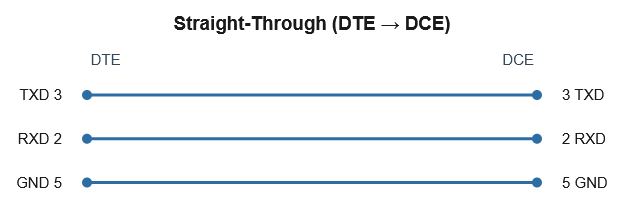
Straight-through
Every pin connects to the same pin: 1 to 1, 2 to 2, 3 to 3, and so on. This is for connecting a DTE to a DCE — a computer to a modem, the classic case. TXD on the DTE lands on TXD at the modem, which is correct, because the modem expects to receive on the line the standard calls TXD.
Null modem
Connect two DTEs directly — two PCs, or a PC to a PLC programming port that is also a DTE — and a straight cable fails. Both ends transmit on pin 3, so the two outputs fight and nothing is received. A null modem cable crosses the lines so each transmitter reaches the other side’s receiver.
The minimum is three wires with TXD and RXD swapped:
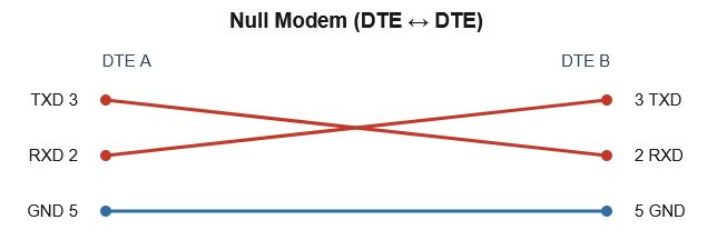
That handles software-only flow control. If one end checks hardware lines before it will talk, you have two options. Run a full null modem that also crosses the handshakes (RTS to CTS, and DTR to DSR plus DCD, both directions), or fool each end with a local loopback: tie pin 7 to pin 8 at the same connector, and tie pins 4, 6, and 1 together at the same connector. The device then sees its own “ready” signal come straight back and stops waiting. The loopback trick is faster to build and solves most stubborn ports.
RS-232 in Industrial Systems
RS-232 looks dated next to Ethernet, but it has not left the plant floor. Knowing where it still shows up saves time when you meet a DB9 on a panel.
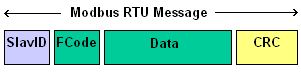
RS-232 vs RS-485 for Modbus
This is the comparison that matters most for automation. RS-232 is single-ended and point-to-point: one driver, one receiver, voltages referenced to a shared ground, and a practical reach of around 15 m. RS-485 is differential and multi-drop: it carries each signal as the difference between two wires, shrugs off noise, runs to roughly 1200 m, and supports many devices on one bus. The full trade-off is covered in RS-485 vs RS-232. Modbus RTU runs over both, but a multi-drop RTU network is almost always RS-485. RS-232 shows up for a single RTU device, a local HMI link, or a service port. If you’re wiring a serial Modbus segment with more than two devices, you want RS-485, not this connector.
The same point applies to other serial-based SCADA protocols. DNP3 and IEC 60870-5-101 both run over serial links, and the connector you meet in the field is often this DB9.
PLC and RTU ports
Many controllers still carry a DB9 for programming or local serial. Older Modicon, Allen-Bradley, and Siemens units used it heavily, and plenty are still in service. The catch: industrial vendors rarely honor the full modem-era pinout. Most use pins 2, 3, and 5 only, and some borrow RTS to drive transmit-enable on an RS-485 converter. Always check the device manual before assuming standard signal meanings on industrial gear.
Console cables
Managed industrial switches and routers often expose a console port as an RJ45 jack, reached with a “DB9-to-RJ45” rollover cable from a laptop’s serial port or a USB-to-serial adapter. Same RS-232 electricals, different connector on the device end. When a switch console shows nothing, the usual culprits are the wrong rollover wiring or a baud rate mismatch, not the hardware.
RS-232 vs USB
A lot of people reach this page holding a USB-to-serial adapter, so it’s worth being clear about why that adapter exists. RS-232 and USB are not two flavors of the same thing. They are different buses that happen to both move data over a cable.
USB is packet-based. A host controls the bus, devices enumerate when you plug them in, and data travels in framed packets over a differential pair. It carries power, supports many devices through hubs, and is hot-pluggable by design.
RS-232 is asynchronous serial. There is no host, no enumeration, and no packets. Each byte is framed by a start bit and one or more stop bits, clocked by an agreed baud rate rather than a shared clock line, and sent as a bipolar voltage referenced to ground. Two devices, one link, and both ends have to be set to the same speed and framing or it fails.
Because of that, USB cannot connect directly to RS-232 signals. You can’t wire a USB data pair to TXD and RXD and expect anything to happen — the voltages, the framing, and the whole signaling scheme are incompatible. The two buses don’t speak to each other at any level.
That gap is exactly what a USB-to-RS232 adapter fills. Inside the connector shell is a bridge chip that does three jobs: it enumerates on the USB side as a device, it runs a UART to handle the async serial framing, and it drives a line transceiver that shifts logic levels up to true RS-232 voltages (the ±3 to ±15 V swing). The operating system loads a driver for the chip and presents it as a virtual COM port, so your software talks to it as if a real serial port were still on the machine.
Choosing a USB-to-RS232 Adapter
Most adapters work fine on a desk. The ones that cause grief in the field almost always come down to the bridge chip and its drivers, so that’s what to look at before you buy.
Chipset is the thing that matters. Two families dominate:
- FTDI (FT232 and similar) is the safer choice for industrial and long-term use. Drivers are stable, well-maintained across Windows and Linux, and the parts behave predictably. The one caution is counterfeits: fake FTDI chips have caused driver headaches in the past, so buy from a source you trust.
- Prolific (PL2303) is cheaper and everywhere, but it’s also the source of most adapter complaints. Older variants are flagged as unsupported on current Windows, show up with a yellow warning in Device Manager, and need you to hunt down a specific legacy driver. Clones make it worse.
Driver issues are the usual failure mode, not the cable. If an adapter installs but won’t pass data, check Device Manager for a warning on the port, confirm the right driver version, and be suspicious of a counterfeit chip on the cheapest units. A genuine FTDI-based adapter avoids most of this.
Windows COM ports are worth understanding. The adapter shows up under Ports (COM & LPT) as a virtual port — COM3, COM4, and so on. The number can change depending on which USB socket you use, and some older software only accepts low COM numbers. You can reassign the port number in Device Manager under the port’s advanced properties, which fixes software that’s hard-coded to a specific COM number.
For anything that has to run unattended on a plant floor, the short version is: pick a genuine FTDI-based adapter, set a fixed COM number, and you remove most of the variables before they bite you.
Field Troubleshooting
When a link won’t work, the fault is almost always wiring, settings, or handshaking. This table maps the symptom to the likely cause and the fastest check.
| Symptom | Likely cause | Check / fix |
|---|---|---|
| No data either direction | TXD and RXD not crossed, or open cable | Confirm null modem vs straight-through; meter continuity on pins 2, 3, 5 |
| Garbage characters | Baud rate, parity, or stop bits mismatch | Match both ends (e.g. 9600 8N1); confirm the same framing |
| Works one way only | One data line broken or miswired | Trace TXD→RXD for each direction separately |
| Port won’t open / device hangs | Waiting on DSR, DCD, or CTS | Loop handshakes locally (7–8, and 1–4–6) or run a full null modem |
| TXD reads 0 V to ground | Dead driver or open line | Idle TXD should read negative (−5 to −12 V); if not, suspect the port or cable |
| Intermittent over distance | Cable too long, noise, or ground offset | Shorten the run, improve shielding/ground; consider RS-485 instead |
| USB adapter: wrong or missing COM port | Driver not loaded, or counterfeit chip | Check Device Manager → Ports; install the correct driver; set a fixed COM number; prefer genuine FTDI |
Frequently Asked Questions
Is it a DB9 or a DE-9?
Technically DE-9. The middle letter is the shell size, and a 9-pin D-sub uses the E shell. “DB9” is the popular name and refers to the same connector, so the two are used interchangeably in practice.
What’s the difference between RS-232 and DB9?
They aren’t the same thing. RS-232 is the electrical standard — voltage levels, signal meanings, timing. DB9 is just a connector that commonly carries RS-232. You can run RS-232 over other connectors, and a DB9 can carry signals other than RS-232.
What’s the minimum number of pins I need?
Three: TXD (3), RXD (2), and GND (5), as long as both ends don’t require hardware handshaking. If a device waits on the control lines, you also have to satisfy them with a full cable or a local loopback.
Why does my TX pin read a negative voltage?
That’s correct. An idle RS-232 data line sits in the MARK state, which is a negative voltage. Reading roughly −5 to −12 V on TXD against ground means the driver is alive. Zero usually means a dead port or open cable.
Can I connect two PCs with a straight DB9 cable?
No. Both PCs are DTEs and both transmit on pin 3, so their outputs collide. You need a null modem cable that crosses TXD and RXD.
What’s the maximum cable length?
The standard limits the load capacitance rather than fixing a length, but a common rule of thumb is about 15 m at higher baud rates, with longer runs possible at slower speeds and with good cable. For long distances, RS-485 is the better choice.
Is RS-232 still used in industrial systems?
Yes. It remains common on PLC and RTU programming ports, single-device Modbus links, instrument connections, and switch console ports. It’s point-to-point and short-range, but for those jobs it’s simple and reliable.
Can USB connect directly to RS-232?
No. USB is a packet-based, host-controlled bus and RS-232 is asynchronous serial with bipolar voltage levels. The two are incompatible at the signal level. A USB-to-RS232 adapter bridges them with a chip that enumerates on USB, runs a UART, and drives the RS-232 voltages, then shows up as a virtual COM port.
Which USB-to-RS232 adapter chipset is most reliable?
For industrial and long-term use, genuine FTDI-based adapters tend to give the fewest driver problems. Prolific (PL2303) adapters are cheaper but more prone to driver and counterfeit issues, especially on current Windows versions.