
On a Modbus serial line, every byte you send is wrapped in a few extra bits before it hits the wire. Those extra bits — the start bit, an optional parity bit, and one or two stop bits — make up the character format. Get them wrong on one device and it won’t talk to the rest of the bus, even if everything else is configured perfectly.
This page covers how RTU and ASCII frame each character, what the parity bit actually does, and where a parity check stops being useful.
Table of Contents
At a glance
| Mode | Start bit | Data bits | Parity bit | Stop bits | Total bits |
|---|---|---|---|---|---|
| RTU, with parity | 1 | 8 | 1 | 1 | 11 |
| RTU, no parity | 1 | 8 | 0 | 2 | 11 |
| ASCII, with parity | 1 | 7 | 1 | 1 | 10 |
| ASCII, no parity | 1 | 7 | 0 | 2 | 10 |
Two things to notice right away. RTU characters are always 11 bits and ASCII characters are always 10 bits — dropping parity doesn’t shrink the frame, it just swaps the parity bit for a second stop bit. And in every case the data bits go out least significant bit first.
The character frame, bit by bit
RTU: 8 data bits per character
In RTU mode each 8-bit byte travels as an 11-bit frame: one start bit, eight data bits, one parity bit, and one stop bit. All eight bits carry real data, which is why RTU packs more into the same baud rate than ASCII does.
The bits leave in this order: start bit, then data bit 0 (LSB) through data bit 7 (MSB), then parity, then stop.
ASCII: 7 data bits per character
ASCII mode sends each byte as two ASCII characters, one per nibble. Each of those characters is a 10-bit frame: one start bit, seven data bits, one parity bit, one stop bit. Seven data bits is enough because all transmitted characters belong to the standard 7-bit ASCII set — the hex characters 0–9 and A–F, plus the frame delimiters.
So a single byte like 0x5B goes out as "5" (0x35) and "B" (0x42) — two 10-bit characters instead of one. That’s the trade: ASCII is easier on the timing but roughly half the throughput.
What the parity bit does
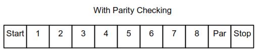
A parity bit is a single extra bit added to each character so the receiver can run a quick error test — a parity check — on what it received. Before a character is sent, the transmitter counts the number of 1 bits in the data portion — seven bits for ASCII, eight for RTU — and sets the parity bit so the total matches the parity mode you configured.
- Even parity: the parity bit is set so the count of
1bits (data + parity) is even. - Odd parity: the parity bit is set so the count is odd.
Worked example, using the eight data bits 1100 0101. That’s four 1 bits.
- With even parity, the count is already even, so the parity bit is
0. Total stays at four. - With odd parity, the parity bit is
1, pushing the count to five.
On the receiving side the device counts the 1 bits the same way and flags an error if the result doesn’t match its configured parity. Both ends have to agree — every device on the line must use the same parity method, or nothing lines up.
Why “no parity” needs two stop bits
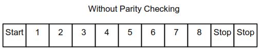
You can turn parity off, but the spec requires a second stop bit when you do. The reason is the character frame format. An asynchronous UART is configured for a fixed frame format — data bits, parity, and stop bits. Removing the parity bit changes that format, so an additional stop bit is used to maintain the expected character length: 11 bits for RTU, 10 for ASCII. The framing stays consistent whether parity is on or off.
That’s why the totals in the table never change: 8 data + 1 parity + 1 stop and 8 data + 0 parity + 2 stop both come to 11.
What parity can and can’t catch
Parity is cheap, but it only catches errors where an odd number of bits flip inside a character.
If two bits get corrupted — say two 1 bits drop out of a character that had three — the count is still odd, and an odd-parity check sees nothing wrong. Any even number of flipped bits slips straight through.
This is why parity is never the only line of defense. Modbus pairs character-level parity with a frame-level check across the whole message:
- RTU uses a 16-bit CRC.
- ASCII uses an 8-bit LRC.
Parity should be applied to each character; the frame check must be applied to the entire message. The two work together — parity catches most single-bit hits early, and the CRC or LRC covers the multi-bit cases parity misses.
One detail worth remembering: the parity bit, start bit, and stop bits are not included in the CRC or LRC calculation. Only the data bits feed the frame check.
Defaults and configuration
Even parity is the required default. A device may also offer odd parity or no parity, but if you don’t configure anything, it should come up in even. The spec also recommends supporting no-parity mode for the sake of compatibility with other products, even though it isn’t mandatory.
Where a device lands depends on its implementation class:
- Basic class devices use even parity, full stop.
- Regular class devices start at even but let you configure no parity and odd parity as well.
The practical takeaway for commissioning: pick one parity setting and one transmission mode, then apply them to every device on the segment. Mixed parity or a mix of RTU and ASCII on the same line will not communicate.
FAQ
What is the default parity for Modbus serial line?
Even parity. Odd and no parity are allowed as options, but even is the required default, and a Basic-class device only supports even.
How many bits are in a Modbus RTU character?
Eleven. That’s one start bit, eight data bits, one parity bit, and one stop bit. With parity disabled it’s one start bit, eight data bits, and two stop bits — still eleven.
How many bits are in a Modbus ASCII character?
Ten. One start bit, seven data bits, one parity bit, one stop bit. Seven data bits is enough because all transmitted characters belong to the standard 7-bit ASCII set.
Why does no parity require two stop bits?
To keep the character frame format consistent. A UART is configured for a fixed frame — data bits, parity, and stop bits — so removing the parity bit is offset by a second stop bit to hold the expected character length: 11 bits for RTU, 10 for ASCII.
Can Modbus parity detect every transmission error?
No. Parity only detects an odd number of flipped bits in a character. Two flipped bits, or any even number, go undetected. That’s why Modbus also runs a CRC (RTU) or LRC (ASCII) across the whole frame.
Do all devices on a Modbus line need the same parity?
Yes. Parity, transmission mode, and serial port settings must match across every device on the segment, or the frames won’t be interpreted correctly.