
HSR gives you zero recovery time. That part is guaranteed by the protocol. What’s not guaranteed — and what the standard deliberately leaves to implementation — is how much latency each node adds to the ring. That accumulates. Get the ring sizing wrong and you can end up with end-to-end delays that cause problems for time-sensitive applications, even on a perfectly healthy network.
This article explains how latency builds up in an HSR ring, what drives it, and how to size your ring with that in mind.
Table of Contents
How a Frame Travels the Ring
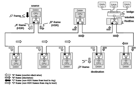
In HSR (Mode H — the mandatory default), every DANH receives a frame on one port and forwards it out the other port. It does this for every frame it doesn’t discard as a duplicate or absorb as the intended destination. Every node in the ring touches every frame.
That’s the fundamental difference between HSR and a switched Ethernet network. In a switch-based network, a frame goes source → switch → destination. In HSR, a frame goes source → node 1 → node 2 → node 3 → … → destination. Every node between sender and receiver adds delay.
The standard defines the switching logic as hardware that “transmits a frame from one port to another port, possibly providing cut-through switching.” That word possibly matters. Cut-through and store-and-forward are both valid implementations, and they behave very differently under load.
Two Types of Forwarding Delay
Cut-through switching starts forwarding a frame before it’s fully received — typically after the destination MAC address has been read. Forwarding delay is small and relatively constant, usually in the range of a few microseconds per node depending on the hardware.
Store-and-forward switching receives the entire frame, checks it for errors, then forwards it. Forwarding delay depends on frame size. A 64-byte frame takes much less time to store and forward than a 1518-byte frame. On a 100 Mbit/s link, a maximum-size Ethernet frame takes about 122 microseconds just to transmit. Multiply that by the number of nodes between sender and receiver and the numbers get significant fast.
IEC 62439-3 does not mandate cut-through switching. It allows it. If your ring nodes use store-and-forward — which many do — frame size becomes a direct factor in ring latency.
The Latency Equation
End-to-end latency in an HSR ring is roughly:
Total latency = (number of hops × per-node forwarding delay) + propagation delay
Where:
- Number of hops = number of nodes between sender and receiver on the shorter path
- Per-node forwarding delay = depends on cut-through vs store-and-forward, and on frame size for the latter
- Propagation delay = cable length ÷ speed of light in the medium (~5 ns/m for copper) — usually negligible in substation environments
Because HSR sends frames in both directions simultaneously, the receiver always processes the first arriving copy — the one that took the shorter path. Worst-case effective latency is therefore bounded by approximately ⌊N/2⌋ hops, not N−1.
For unicast traffic, nodes operating in Mode H discard frames once the destination has received it. The frame stops circulating as soon as it reaches the target. For multicast, both copies traverse the full ring, but latency is still determined by the shorter path arriving first.
What the Standard Says About Node Modes
IEC 62439-3 defines six DANH operating modes. Mode H is mandatory. The others are optional.
Mode H (mandatory): Full HSR-tagged forwarding. Every node forwards every frame unless it’s a duplicate, sent by the node itself, or the node is the unique destination. This is the standard ring behavior.
Mode X (optional): Mode X suppresses forwarding of frames already received from the opposite direction, reducing redundant traffic but not affecting primary latency.
Mode U (optional): Unicast forwarding — the node forwards frames even if it is the unique destination, rather than absorbing them. Used in specific topologies.
Mode N (optional): No forwarding. The node does not pass ring traffic from port to port. This breaks the ring for other traffic, so it’s only used during testing or maintenance.
For latency purposes, Mode H is what you design around. Mode X can help reduce traffic volume on busy rings, but it doesn’t change the fundamental per-hop forwarding delay.
QuadBoxes Do Not Help Latency
This is stated explicitly in the standard: connecting HSR rings through QuadBoxes does not improve end-to-end transmission delay. A QuadBox adds forwarding delay just like any other node — one at each ring boundary. Splitting a large ring into two smaller rings connected by QuadBoxes reduces the number of nodes per ring, which can help, but the QuadBoxes themselves add hops.
If you’re splitting a ring to reduce latency, do the math. Segmenting a ring can reduce per-ring hop count, but QuadBoxes add additional forwarding stages, so overall latency improvement depends on traffic paths.
Practical Sizing Guidelines
The standard does not specify a maximum number of nodes per ring. That’s intentional — it depends on your hardware, your traffic profile, and your latency budget. But here are the factors to work through:
1. Know your forwarding delay per node Get this from the vendor datasheet. Ask specifically whether the device uses cut-through or store-and-forward switching. If store-and-forward, get the forwarding delay for your maximum frame size.
2. Know your worst-case hop count For a ring of N nodes, the effective worst-case latency is based on approximately ⌊N/2⌋ hops — the shorter of the two paths, since both directions are transmitted simultaneously and the receiver processes whichever arrives first. For multicast (GOOSE, SV), latency is still determined by the shorter path, but both copies traverse the full ring.
3. Set a latency budget before you design IEC 61850 GOOSE messages for protection applications typically need end-to-end delivery within 4 ms (Performance Class P1) or less. Work backward from that budget: subtract cable propagation delay, application processing time at sender and receiver, and any RedBox or QuadBox hops. What’s left is your allowance for ring forwarding delay.
4. Keep multicast in mind GOOSE and Sampled Values are multicast. They traverse the full ring regardless of where the publisher and subscriber sit. If your ring has heavy GOOSE or SV traffic, that’s the traffic that defines your latency exposure — not unicast.
5. Avoid mixing latency-sensitive and bandwidth-heavy traffic on the same ring without VLANs A single large frame from a file transfer can add over 100 µs of store-and-forward delay at each node. In a ring with 20 nodes, that’s potentially 2 ms of jitter from a single interfering frame. VLAN segregation and QoS prioritization don’t eliminate this in store-and-forward architectures — they only reduce the probability of interference.
Example: 20-Node Ring, Protection Application
Setup:
- 20 DANHs on a single HSR ring
- Store-and-forward switching, 100 Mbit/s
- Maximum frame size: 1518 bytes → ~122 µs transmission time per link
- Per-node forwarding delay (store-and-forward): ~200 µs worst case (varies by hardware)
- GOOSE publisher and subscriber on opposite sides of the ring: ~10 hops (shorter path)
Rough worst-case calculation:
| Component | Value |
|---|---|
| Effective hops (shorter path) | ~10 |
| Per-hop delay | 200 µs |
| Ring forwarding total | 2,000 µs (2 ms) |
| Propagation delay (200 m cable) | ~1 µs |
| Total | ~2 ms |
That leaves roughly 2 ms of budget for application processing at sender and receiver. On a ring of 30 nodes, the same calculation gives ~3 ms of forwarding delay alone — still within P1 on cut-through hardware, but tight or over budget on store-and-forward depending on vendor implementation.
Checklist Before You Finalize Ring Size
- Confirmed cut-through or store-and-forward on all nodes (including RedBoxes and QuadBoxes)
- Per-node forwarding delay obtained from vendor at maximum frame size
- Worst-case hop count calculated for your most latency-sensitive traffic flow
- Latency budget defined from application requirements (IEC 61850 performance class)
- Multicast traffic (GOOSE, SV) accounted for — full ring traversal, always
- VLAN and QoS strategy defined if mixed traffic types are on the same ring
- If using QuadBoxes: latency recalculated including QuadBox forwarding delay at ring boundaries
Conclusion
HSR’s zero recovery time is unconditional. The latency it adds is not. Every node on the ring contributes forwarding delay, and that cost compounds with ring size, frame size, and switching architecture.
The good news is the math is straightforward. Get the per-hop forwarding delay from your vendor, count your hops on the shorter path, and check it against your IEC 61850 performance class budget before you finalize the design. Do it for your heaviest multicast flows — GOOSE and SV don’t get to take the short path.
If the numbers don’t fit, the options are: smaller rings, cut-through hardware, or splitting rings through QuadBoxes — with the understanding that QuadBoxes add their own forwarding stages and don’t automatically improve the result. There’s no shortcut. Size it on paper first.