
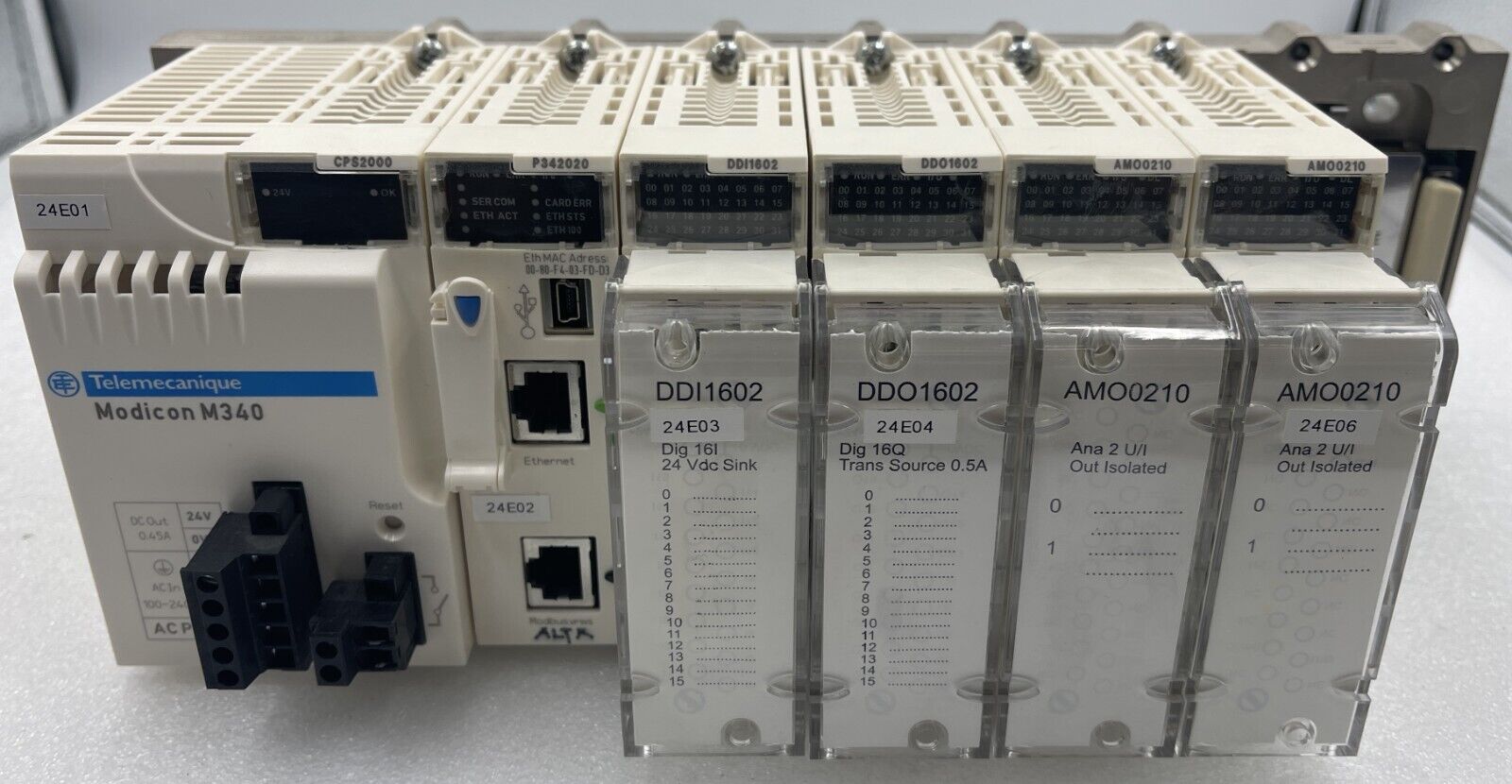
The Schneider Modicon M340 PLC is one of the most widely deployed PLCs in Europe, the Middle East, and Africa for water treatment, building automation, energy management, and machine control. Modbus TCP is its default Ethernet protocol — the embedded CPU Ethernet port is a Modbus TCP server out of the box.
This guide shows you how to configure the M340 for Modbus TCP communication using Unity Pro or its successor EcoStruxure Control Expert. It covers both directions: the M340 as a server (slave) responding to a SCADA master, and the M340 as a client (master) reading data from another Modbus TCP device.
Table of Contents
1. M340 Hardware Options for Modbus TCP
The M340 supports Modbus TCP through three hardware options:
| Option | Modbus TCP Support | Use Case |
|---|---|---|
| CPU embedded Ethernet port (BMX P34 2020 / 2030) | Server + Client | Default option for most applications |
| BMX NOE 0100 Ethernet module | Server + Client (with IO Scanning) | Larger systems, IO Scanning to remote devices |
| BMX NOC 0401 Ethernet module | Server + Client | Multi-protocol (Modbus TCP + EtherNet/IP) |
For most projects, the CPU embedded Ethernet port is sufficient. Add an NOE 0100 only if you need IO Scanning or higher connection count. Add an NOC 0401 only if you need EtherNet/IP alongside Modbus TCP.
2. Modbus TCP on the CPU Embedded Ethernet Port
The BMX P34 2020 and BMX P34 2030 CPUs have a built-in Ethernet port that runs Modbus TCP server automatically — no special configuration needed for basic server functionality.
Step 1. Open the Project
- Launch EcoStruxure Control Expert (or Unity Pro)
- Open your project or create a new one with a BMX P34 2020 / 2030 CPU
Step 2. Configure the Ethernet Port
- In the Project Browser, expand Configuration → 0: PLC Bus → CPU
- Double-click the CPU to open its configuration window
- Click the Ethernet tab
Step 3. Set IP Configuration
| Field | Example Value |
|---|---|
| IP Address | 192.168.1.10 |
| Subnet Mask | 255.255.255.0 |
| Gateway Address | 192.168.1.1 |
| IP Configuration Mode | Configured (recommended) |
Step 4. Configure Modbus TCP Server Settings
In the Ethernet configuration:
- Confirm Modbus Server is enabled (default: enabled)
- Confirm TCP port: 502 (the standard Modbus TCP port — do not change unless required)
- Set Slave Address (Unit ID) if needed (default: 255 — accepts any Unit ID)
Step 5. Build and Download
- Build → Rebuild All Project
- PLC → Connect → Transfer Project to PLC
- Set the PLC to RUN
The M340 is now a Modbus TCP server. Any Modbus TCP master can connect to its IP address on port 502 and read/write data.
3. Modbus TCP on the BMX NOE 0100 Module
The BMX NOE 0100 is an Ethernet communication module that adds:
- A second Ethernet port
- IO Scanning (cyclic Modbus TCP polling, configured in the DTM Browser)
- Up to 64 simultaneous Modbus TCP connections
When to Use NOE 0100
- Need to isolate Modbus TCP traffic from the CPU port
- Need IO Scanning to read from many remote Modbus TCP devices automatically
- Larger systems requiring more connections than the CPU port supports
Configuration
- Add the BMX NOE 0100 to your rack in the Project Browser
- Double-click the module to configure
- Set IP address, subnet, gateway
- Enable Modbus Server in the IO Configuration tab
- For IO Scanning, configure the slave list (IP addresses, Unit IDs, register ranges)
4. Modbus TCP on the BMX NOC 0401 Module
The BMX NOC 0401 is a 4-port Ethernet module that supports both Modbus TCP and EtherNet/IP simultaneously. Common in plants integrating Schneider PLCs with Allen-Bradley or other EtherNet/IP devices.
Port Designations
| Port | Use |
|---|---|
| Port 1 | Configurable for Modbus TCP or EtherNet/IP |
| Port 2 | Configurable for Modbus TCP or EtherNet/IP |
| Ports 3, 4 | Programming and diagnostic access only — not for Modbus TCP server/client |
⚠️ Important: Ports 3 and 4 of the NOC 0401 are designated for programming/diagnostic connections only. Do not attempt to use them for permanent Modbus TCP communication.
Configuration
- Add the BMX NOC 0401 to your rack
- Open the DTM Browser (Tools → DTM Browser)
- Navigate to the NOC 0401 device
- Configure each port for the required protocol
- Set IP addresses (each port needs a unique IP)
5. M340 as Modbus TCP Server (Slave)
When the M340 is the server, a SCADA master or another PLC connects to it on port 502 and reads/writes its memory.
Default Behavior
- No code is required for basic Modbus TCP server functionality on the CPU embedded port
- Any external Modbus TCP master can connect and exchange data
Memory Mapping
The Modbus master reads/writes M340 internal memory. Schneider’s mapping:
| Modbus Reference | M340 Memory | Function Codes |
|---|---|---|
| 0xxxx (Coils, read/write) | %M (internal bits) | FC 01, FC 05, FC 15 |
| 1xxxx (Discrete Inputs, read-only) | %M (internal bits) — same memory as 0xxxx | FC 02 |
| 3xxxx (Input Registers, read-only) | %MW (internal words) — same memory as 4xxxx | FC 04 |
| 4xxxx (Holding Registers, read/write) | %MW (internal words) | FC 03, FC 06, FC 16 |
💡 Schneider quirk: Coils (%M) and Discrete Inputs share the same memory. Holding Registers and Input Registers also share the same memory. When the master reads “Discrete Input 1”, it reads %M0 — the same bit as “Coil 1”. This is unusual; most PLCs separate these areas.
Address Offset
| Modbus Address (master view) | M340 Internal Address |
|---|---|
| 40001 (Holding Register 1) | %MW0 |
| 40002 | %MW1 |
| 40100 | %MW99 |
| 1 (Coil 1) | %M0 |
| 100 (Coil 100) | %M99 |
The master uses Modbus addresses starting at 1; M340 internal memory starts at 0. Always subtract 1.
6. M340 as Modbus TCP Client (Master)
When the M340 needs to read or write data on another Modbus TCP device (a remote I/O, energy meter, VFD), you use function blocks in the program.
The two main function blocks are:
- READ_VAR — reads data from a remote Modbus device
- WRITE_VAR — writes data to a remote Modbus device
These work with both Modbus TCP and Modbus serial. For TCP, the address is built using the ADDM function.
7. The READ_VAR Function Block
READ_VAR reads variables from a remote Modbus device. Typical use:
READ_VAR(
    ADR := address,         // ADDM result — target device address
    OBJ := '%MW',           // Object type to read: '%MW' (HR), '%M' (Coils), '%IW' (IR)
    NUM := 0,               // Starting register (0-based)
    NB := 10,               // Number of registers to read
    GEST := management_array, // 4-word management array
    RECP := receive_array   // Array to store received data
);
Parameters
| Parameter | Type | Description |
|---|---|---|
| ADR | ARRAY[0..5] OF INT | Target device address (build with ADDM) |
| OBJ | STRING | Object type: '%MW', '%M', '%IW', '%I' |
| NUM | DINT | Starting address (0-based) |
| NB | INT | Number of objects to read |
| GEST | ARRAY[0..3] OF INT | Management array (status, length, timeout, exchange ID) |
| RECP | Array of INT/EBOOL | Received data |
Example: Read 10 Holding Registers
addr_array : ARRAY[0..5] OF INT;
mgmt : ARRAY[0..3] OF INT;
data_received : ARRAY[0..9] OF INT;

// Build address (target = 192.168.1.20, Unit ID 1)
ADDM(IN := '0.0.0.{192.168.1.20}1', OUT => addr_array);

// Read holding registers 0–9 from target
READ_VAR(ADR := addr_array,
         OBJ := '%MW',
         NUM := 0,
         NB := 10,
         GEST := mgmt,
         RECP := data_received);
GEST (Management) Array
| Index | Meaning |
|---|---|
| 0 | Exchange number (auto-managed) |
| 1 | Communication report (status: 0 = OK) |
| 2 | Length / response code |
| 3 | Timeout (in 100ms units, e.g., 10 = 1 second) |
Always check GEST[1] for errors. Common values:
| GEST[1] | Meaning |
|---|---|
| 0 | Success |
| 1 | Exchange stopped on timeout |
| 2 | Exchange stopped by user |
| 4 | Bad parameters or address |
| 5 | Unknown destination |
| 7 | TCP connection interrupted |
8. The WRITE_VAR Function Block
WRITE_VAR writes data to a remote Modbus device. Same pattern as READ_VAR.
WRITE_VAR(
    ADR := addr_array,      // ADDM result
    OBJ := '%MW',           // Object type
    NUM := 100,             // Starting register (0-based)
    NB := 5,                // Number of registers to write
    EMIS := data_to_send,   // Data array
    GEST := mgmt
);
Example: Write 5 Holding Registers
data_to_send : ARRAY[0..4] OF INT := [1234, 5678, 0, 1, 9999];

WRITE_VAR(ADR := addr_array,
          OBJ := '%MW',
          NUM := 100,
          NB := 5,
          EMIS := data_to_send,
          GEST := mgmt);
This writes 5 registers to the target device starting at register 100 (PDU address) using FC 16 (Write Multiple Registers).
9. The ADDM Function Block
The ADDM block builds the address structure used by READ_VAR and WRITE_VAR.
Syntax for Modbus TCP
ADDM(IN := 'r.m.c.{IP_address}UnitID', OUT => addr_array);Where:
| Field | Meaning | Example |
|---|---|---|
| r | Rack number | 0 (CPU embedded port) |
| m | Module slot | 0 (CPU port), or NOC slot number |
| c | Channel | 0 |
| IP_address | Target IP | 192.168.1.20 |
| UnitID | Target Unit ID | 1 (or 255 for “any”) |
Examples
// Target via CPU embedded Ethernet port:
ADDM(IN := '0.0.0.{192.168.1.20}1', OUT => addr_array);

// Target via NOC 0401 in slot 3, port 1:
ADDM(IN := '0.3.0.{192.168.1.20}1.TCP.MBS', OUT => addr_array);

// Target via gateway (Unit ID 5 behind a Modbus TCP gateway):
ADDM(IN := '0.0.0.{192.168.1.30}5', OUT => addr_array);
The .TCP.MBS suffix is required for the NOC 0401 to indicate Modbus TCP transport.
10. M340 Memory Mapping for Modbus
| Memory Type | Schneider Notation | Modbus Reference (Master Sees) |
|---|---|---|
| Internal bits | %M0, %M1, %M100, … | Coils 1, 2, 101, … (0xxxx) |
| Internal bits (read-only view) | %M (same as above) | Discrete Inputs 1, 2, … (1xxxx) |
| Internal words | %MW0, %MW1, %MW100, … | Holding Registers 40001, 40002, 40101, … (4xxxx) |
| Internal words (read-only view) | %MW (same) | Input Registers 30001, 30002, … (3xxxx) |
Important: Configure Memory Size
Before downloading the project, ensure enough memory is allocated:
- Tools → Project Settings → PLC Embedded Data
- Set %M size (e.g., 1024 bits)
- Set %MW size (e.g., 1024 words)
- Build → Rebuild All Project
Without sufficient %M and %MW allocation, the master will receive Exception 02 (Illegal Data Address) when trying to access unmapped memory.
11. Function Code Limitations and Workarounds
What the DTM Browser / IO Scanning Supports
When using the DTM Browser to configure IO Scanning (NOE 0100):
| Modbus Function | Supported by DTM Browser |
|---|---|
| FC 03 (Read Holding Registers) | Yes |
| FC 16 (Write Multiple Registers) | Yes |
| FC 23 (Read/Write Multiple Registers) | Yes |
| FC 01 (Read Coils) | Function blocks only |
| FC 02 (Read Discrete Inputs) | Function blocks only |
| FC 04 (Read Input Registers) | Function blocks only |
Workaround for FC 01, 02, 04
To read coils (1xxxx, 0xxxx) or input registers (3xxxx) from a remote device, use READ_VAR with the appropriate OBJ value:
| OBJ Value | Function Code | Reads |
|---|---|---|
'%MW' | FC 03 | Holding Registers (4xxxx) |
'%IW' | FC 04 | Input Registers (3xxxx) |
'%M' | FC 01 | Coils (0xxxx) |
'%I' | FC 02 | Discrete Inputs (1xxxx) |
This is the answer to one of the most common M340 community questions: “How do I read 30001 input registers?” — Answer: use READ_VAR with OBJ := '%IW'.
12. Reading Input Registers (3xxxx) and Discrete Inputs (1xxxx)
Read 10 Input Registers Starting at Register 30001
ADDM(IN := '0.0.0.{192.168.1.20}1', OUT => addr_array);

READ_VAR(ADR := addr_array,
         OBJ := '%IW',           // %IW = Input Registers (FC 04)
         NUM := 0,               // 30001 → PDU address 0
         NB := 10,
         GEST := mgmt,
         RECP := input_data);
Read 16 Discrete Inputs Starting at 10001
READ_VAR(ADR := addr_array,
         OBJ := '%I',            // %I = Discrete Inputs (FC 02)
         NUM := 0,
         NB := 16,
         GEST := mgmt,
         RECP := discrete_inputs);
13. Connection Limits and Performance
Maximum Concurrent Connections
| Hardware | Max Concurrent Modbus TCP Connections |
|---|---|
| BMX P34 2020/2030 CPU embedded port | 6 (some firmware versions: 16) |
| BMX NOE 0100 | 64 |
| BMX NOC 0401 | 64 (per port) |
Performance Recommendations
- Allow at least 100 ms between consecutive READ_VAR/WRITE_VAR to the same device — this prevents race conditions and error 0x07
- Use the GEST[3] timeout parameter — set to 10–50 (1–5 seconds) for typical applications
- For polling many devices, stagger requests instead of sending them simultaneously
- Always gate function blocks with the previous DONE/BUSY status — never trigger READ_VAR if the previous one hasn’t completed
Polling Pattern (Structured Text)
IF NOT read_var_busy AND timer.Q THEN
    timer(IN := FALSE);  // Reset timer
    // Trigger read
    READ_VAR(ADR := addr_array, OBJ := '%MW',
             NUM := 0, NB := 10,
             GEST := mgmt, RECP := data);
    read_var_busy := TRUE;
END_IF;

// Check completion
IF mgmt[0] = 0 AND read_var_busy THEN  // Exchange complete
    read_var_busy := FALSE;
    timer(IN := TRUE, PT := T#100ms);  // Wait 100ms before next
END_IF;
14. Common Errors and Fixes
GEST[1] Error Codes
| Error | Hex | Cause | Fix |
|---|---|---|---|
| 0x01 | 1 | Exchange stopped on timeout | Increase GEST[3] timeout. Check if device is reachable. |
| 0x02 | 2 | Exchange stopped by user | Programmatic stop — review code |
| 0x04 | 4 | Bad parameters or address | Verify ADDM string, OBJ value, NUM and NB ranges |
| 0x05 | 5 | Unknown destination | Wrong IP or Unit ID |
| 0x07 | 7 | TCP connection interrupted | Add 100 ms delay between requests. Check connection limits. |
| 0x09 | 9 | Connection refused | Target device not running Modbus TCP server. Check port 502. |
Modbus Exception Codes (in Slave Response)
| Exception | Cause | Fix |
|---|---|---|
| 01 (Illegal Function) | Slave doesn’t support this FC | Try another OBJ value |
| 02 (Illegal Data Address) | Wrong NUM or NB exceeds slave’s range | Verify slave’s register map |
| 03 (Illegal Data Value) | NB too large (>125 for FC 03/04) | Split into multiple READ_VAR calls |
| 04 (Slave Device Failure) | Internal slave error | Check slave hardware/diagnostics |
For a complete Modbus exception code reference, see: Modbus Exception Codes Explained
15. Troubleshooting Checklist
When Modbus TCP communication fails on the M340, work through this list:
- Ping the target device from a PC on the same network — confirms basic IP connectivity
- Test port 502 with
telnet <ip> 502orTest-NetConnection -Port 502— confirms the slave is listening - Check %S98 (system bit) for global communication errors
- Inspect GEST[1] for the specific error code
- Use Wireshark with capture filter
tcp port 502to see actual frames - Verify memory allocation — Tools → Project Settings → PLC Embedded Data
- Check connection count — for the embedded CPU port, fewer than 6 simultaneous connections
- Confirm IP configuration mode is set to “Configured” (not BOOTP)
- Test with a Modbus TCP simulator like ModRSsim2 to isolate the M340 from the field device
- Check firewall rules between the M340 and target device — port 502 must be open
For Wireshark analysis of Modbus TCP traffic, see: Wireshark for Modbus TCP
Summary
The Schneider M340 supports Modbus TCP through the CPU embedded Ethernet port (default), the BMX NOE 0100, or the BMX NOC 0401. The CPU port works as a Modbus TCP server out of the box without any code.
The key things to remember:
- Server mode needs no code — just enable the embedded Ethernet port
- Client mode uses the READ_VAR and WRITE_VAR function blocks with ADDM for address building
- OBJ value controls which Modbus function code is used:
'%MW'= FC 03,'%IW'= FC 04,'%M'= FC 01,'%I'= FC 02 - GEST array carries status — always check GEST[1] for errors
- The CPU embedded port supports 6 concurrent connections (some firmware: 16). For more, use NOE 0100 or NOC 0401.
- Allocate enough %M and %MW in Project Settings before downloading
- For NOC 0401, only ports 1 and 2 support Modbus TCP — ports 3 and 4 are programming-only
- Add at least 100 ms between consecutive READ_VAR calls to avoid error 0x07