
PRP and HSR both deliver zero-recovery-time redundancy — but they work differently, and mixing them takes more than just plugging cables together. This guide walks through every connection scenario defined in IEC 62439-3, what device you need for each one, and what to watch out for when you’re laying out the topology.
Table of Contents
Before You Start: Know What You’re Connecting
PRP runs on two parallel LANs. Every device sends two copies of every frame — one on LAN A, one on LAN B. Devices that support PRP are called DANPs. Devices that don’t (single-port equipment) are called SANs.
HSR runs on a ring. Every device sends two copies of every frame — one each way around the ring. Devices on the ring are called DANHs. SANs can’t join the ring directly.
Keep those differences in mind as you work through the scenarios below.
Scenario 1: Connecting SANs to an HSR Ring
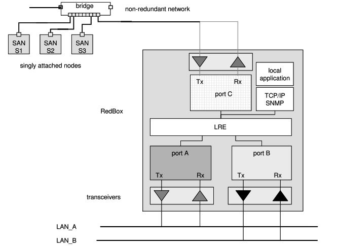
Device needed: RedBox (SAN mode)
A SAN — a single-port device — can’t go directly on the ring. It can’t interpret the HSR tag in incoming frames, and it can’t send frames out two ports. You attach it to a RedBox instead.
The RedBox sits on the ring as a full DANH. Behind it, you connect your SANs on standard Ethernet ports. The RedBox acts as a proxy for all of them — it sends supervision frames on their behalf and handles all the HSR tagging.
Steps:
- Add the RedBox to the ring like any other DANH
- Connect your SANs to the RedBox’s access ports (D1 through Dn)
- Configure the RedBox in SAN mode
- Verify supervision frames are being sent for each SAN
One RedBox can proxy multiple SANs. The RedBox becomes a single point of failure for the SANs connected behind it — if high availability for those devices matters, that’s a design constraint to plan around.
Scenario 2: Connecting a PRP Network to an HSR Ring
Device needed: Two RedBoxes (PRP mode) — one configured as A, one as B
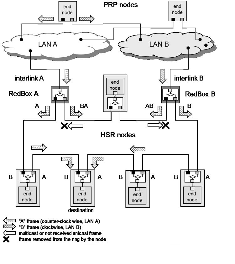
This is where it gets more specific. You can’t use a single RedBox. The PRP network has two LANs — LAN A and LAN B — and each one needs its own RedBox.
RedBox A attaches to LAN A. RedBox B attaches to LAN B. Both RedBoxes connect to the same HSR ring. Each one is configured with a NetId (1 to 6) and a LanId (A=0 or B=1), which together form the 4-bit PathId carried in the HSR tag. This PathId is how the ring tracks which frames came from which LAN and prevents them from being reinjected into the wrong place.
The two RedBoxes coordinate: if RedBox A receives a frame from the ring before it would have sent it itself, it holds back. RedBox B does the same. This prevents duplicates circulating unnecessarily.
Multicast frames and unicast frames with no receiver on the ring are removed by the RedBox that inserted them — not left to circulate.
Steps:
- Assign a NetId to this PRP-HSR connection (1–6; must be unique if multiple PRP networks connect to the same ring)
- Configure one RedBox as A (LanId=0), connect its interlink to LAN A
- Configure the other as B (LanId=1), connect its interlink to LAN B
- Connect both RedBoxes to the HSR ring
- Verify PathId is being set correctly in HSR tags
- Check that frames from LAN A are not being reinjected into LAN B and vice versa
One PRP network can connect to multiple HSR rings — just add another RedBox pair per ring, each with its own NetId.
Scenario 3: Connecting Two HSR Rings Together
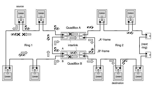
Device needed: Two QuadBoxes — QuadBox A and QuadBox B
A QuadBox is a quadruple-port device: two ports on Ring 1, two ports on Ring 2. It behaves as a full DANH in each ring. Under the hood, it’s two RedBoxes in HSR-HSR mode with an interlink between them.
Two QuadBoxes are required to preserve HSR’s dual counter-rotating traffic paths and ensure redundancy. If one QuadBox fails, the other keeps the rings connected.
Traffic filtering is done by MAC address learning and VLAN filtering. The QuadBox does not forward frames back to the ring they came from.
One important note the standard makes explicit: coupling rings through QuadBoxes does not improve end-to-end transmission delay. You’re adding traffic capacity, not reducing latency.
Steps:
- Install QuadBox A — two ports on Ring 1, two ports on Ring 2
- Install QuadBox B — same rings, same configuration
- Verify each QuadBox is operating as a DANH in both rings
- Confirm MAC address learning and VLAN filtering are active
- Test that a failure of one QuadBox does not interrupt inter-ring communication
Scenario 4: Hierarchical Ring Topology
Device needed: QuadBoxes at each junction
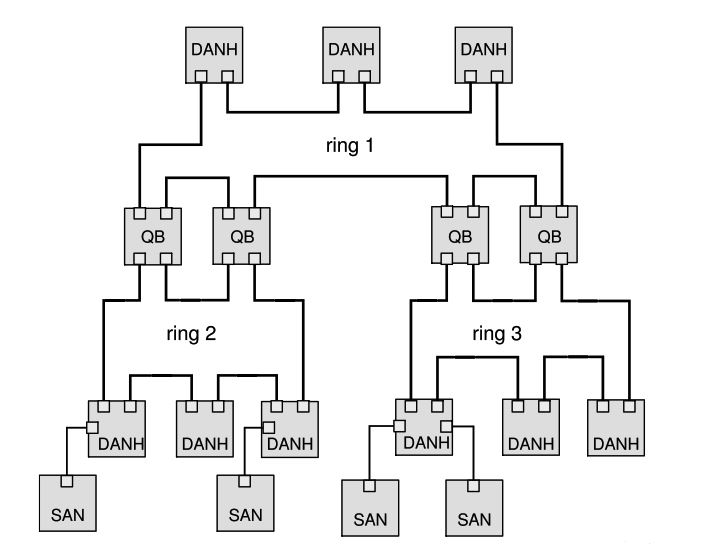
An HSR network can grow into a hierarchy — Ring 1 at the top, Ring 2 and Ring 3 branching off, connected by QuadBoxes. The standard shows this structure in its meshed topology examples.
The frame handling still works the same way. Frames forwarded between rings are not re-duplicated; they retain their original sequence and are treated as part of the same redundancy stream.
The key rule: rings connected by QuadBoxes cannot also be connected back to each other by another QuadBox, or by a PRP network. That would create a loop, and the standard explicitly prohibits it. The topology must be a tree — no cycles.
Steps:
- Map out your ring hierarchy before cabling
- Identify every junction between rings — each one needs a QuadBox pair
- Check the topology for any path that would create a loop — correct it before commissioning
- Verify that no two rings that are already connected via QuadBoxes are also connected through a PRP network
Scenario 5: One PRP Network Connecting to Multiple HSR Rings
Device needed: One RedBox pair per HSR ring
A single PRP network can connect to as many HSR rings as needed. Each ring gets its own RedBox A and RedBox B, each with a unique NetId.
The constraint: the HSR rings connected to the same PRP network cannot be connected to each other. Not by QuadBoxes, not by another PRP network. Any such connection creates a loop. The standard is clear on this — see Figure 19 in IEC 62439-3:2016 for the prohibited topology.
Steps:
- Assign a unique NetId to each ring connection. The NetId is a 3-bit value — usable range is 1 to 6 (NetId 0 is used by regular HSR frames; NetId 7 is reserved), giving a maximum of 6 PRP-to-ring connections from a single PRP network.
- Deploy a RedBox A/B pair for each ring
- Confirm that none of the connected HSR rings have any path between them outside of the PRP network
Topology Rules — Quick Reference
| Connection | Device | Notes |
|---|---|---|
| SAN → HSR ring | RedBox (SAN mode) | One RedBox can serve multiple SANs |
| PRP network → HSR ring | RedBox pair (PRP mode) | One per LAN; configure NetId and LanId |
| HSR ring → HSR ring | Two QuadBoxes (A and B) | Both required — protocol and redundancy |
| PRP network → multiple HSR rings | RedBox pair per ring | Each ring needs a unique NetId |
| HSR ring hierarchy | QuadBox pair per junction | Tree topology only — no loops |
Prohibited:
- Two HSR rings connected by both QuadBoxes and a PRP network (creates a loop)
- A single QuadBox between two rings (breaks HSR dual-path mechanism)
- SANs inserted directly into an HSR ring without a RedBox
Clock Synchronization
If your application requires time synchronization — and in substation automation it almost always does — this needs its own design pass. Don’t assume the redundancy topology handles it automatically.
IEC 62439-3 covers clock synchronization in Annex A (normative). It specifies how PTP clocks operating per IEC 61588 attach over simultaneously active redundant paths in PRP and HSR networks with no single point of failure at the network level. Two PTP profiles are defined in Annex C: L3 E2E (Layer 3 with end-to-end delay measurement) and L2 P2P (Layer 2 with peer-to-peer delay measurement). L2 P2P is mandatory — all clocks shall support peer-to-peer delay measurement. L3 E2E is an additional profile.
In HSR, each DANH implements a Hybrid Clock — it handles PTP messages on both ring ports and applies residence time corrections. RedBoxes also have a defined clock role depending on their mode and position relative to master and slave clocks.
The key point: coupling rings through QuadBoxes adds complexity to the PTP topology. Verify that your grandmaster can reach all slaves through the coupled rings, and that residence time correction is being applied correctly at each hop. Test clock sync independently from redundancy failover testing.
Physical Layer
IEC 62439-3 does not specify cable types, distances, or physical layer requirements. Those are governed by the relevant IEEE 802.3 standards depending on the media you’re using (copper, fiber, SFP). Standard 100BASE-TX or 1000BASE-T for copper, appropriate fiber variants for longer runs.
One practical note: HSR ring latency accumulates with each node in the ring. The standard specifies a maximum ring latency — every node contributes forwarding delay. Keep ring size manageable and factor in the forwarding delay of RedBoxes and QuadBoxes when calculating worst-case end-to-end latency.
Management and IP Addressing
Every RedBox implements at least a management interface — this is stated in the standard (Note 1, section 5.4.1). Assign it a static IP address. The RedBox is itself a DANH (in HSR) or DANP (in PRP) and appears as a node on the network — plan your IP scheme accordingly.
For SANs behind a RedBox, the RedBox proxies their presence on the redundant network. The SANs keep their own IP addresses and are reachable through the RedBox. No special addressing is required for them — they behave like any device on a standard Ethernet segment connected to the RedBox’s access ports.
Example: Substation with PRP Process Bus and HSR Station Bus
Take a typical substation layout: a PRP network at the process level connecting protection IEDs on two LANs, and an HSR ring at the station level carrying SCADA traffic, engineering workstations, and bay controllers. The two levels are connected through a RedBox pair.
Network layout:
- HSR ring (station bus): 10.0.1.0/24
- PRP LAN A (process bus): 10.0.2.0/24
- PRP LAN B (process bus): 10.0.3.0/24
- Management VLAN: 10.0.10.0/24
HSR ring nodes (DANHs):
| Device | IP Address | Notes |
|---|---|---|
| SCADA Server | 10.0.1.10 | Station-level HMI |
| Bay Controller 1 | 10.0.1.11 | |
| Bay Controller 2 | 10.0.1.12 | |
| Bay Controller 3 | 10.0.1.13 | |
| Engineering Workstation | 10.0.1.20 | |
| RedBox A | 10.0.1.30 | Management interface on HSR ring; also on LAN A |
| RedBox B | 10.0.1.31 | Management interface on HSR ring; also on LAN B |
PRP nodes (DANPs) — process bus:
| Device | IP Address | Notes |
|---|---|---|
| Protection IED 1 | 10.0.2.51 | Single IP — LRE handles both ports transparently |
| Protection IED 2 | 10.0.2.52 | |
| Protection IED 3 | 10.0.2.53 | |
| Merging Unit 1 | 10.0.2.61 | |
| Merging Unit 2 | 10.0.2.62 |
RedBox configuration:
- RedBox A: NetId = 1, LanId = A (0) — connected to LAN A
- RedBox B: NetId = 1, LanId = B (1) — connected to LAN B
- PathId carried in HSR tag = NetId + LanId → 0x2 for RedBox A, 0x3 for RedBox B
What this means in practice:
A protection IED at 10.0.2.52 sends a GOOSE message. Its LRE sends two copies simultaneously — one on LAN A, one on LAN B. RedBox A picks it up from LAN A, strips the PRP RCT, wraps it in an HSR tag with PathId 0x2, and injects it into the ring. RedBox B does the same from LAN B with PathId 0x3. The SCADA server at 10.0.1.10 receives both copies and discards the duplicate — exactly as it would for any HSR frame.
A bay controller at 10.0.1.11 sending a command back to the IED goes the other way: the frame circulates the HSR ring, RedBox A and B each receive it, strip the HSR tag, insert the appropriate LAN identifier into the PRP RCT, and forward it onto their respective LANs. The IED receives both copies and discards the duplicate.
The RedBox management interfaces (10.0.1.30 and 10.0.1.31) are reachable from any station bus device. If you want them reachable from a separate management network, assign a second IP on the management VLAN and route accordingly.
Conclusion
PRP and HSR are well-defined protocols, and the connection mechanisms between them are fully specified in IEC 62439-3. The scenarios aren’t complicated once you know which device handles which job — a RedBox for bringing non-redundant devices or PRP networks into an HSR ring, a QuadBox pair for connecting rings to each other.
What causes problems on site is usually not the protocol itself but the details around it: a topology that creates a loop, a single QuadBox deployed where two are needed, clock sync that was never validated across ring boundaries, or a RedBox with no static IP assigned for management. Get those right during the design phase and commissioning becomes straightforward.
Use the topology rules table as a checklist before you cable anything. If the topology you’re drawing has a path that could create a loop, the standard prohibits it — redesign before you build it.