
The DNP3 protocol is a communication standard that moves status, measurement, and control data between a master station and remote field devices. It is standardized as IEEE 1815, and it is the dominant telemetry protocol in North American electric utilities. Water, wastewater, and oil and gas operators use it too.
If you have wired an RTU to a control center, you have almost certainly touched DNP3. This page covers what the protocol actually does on the wire, how its data model is built, and the parts engineers get stuck on in the field.
DNP3 at a glance
| Item | Value |
|---|---|
| Full name | Distributed Network Protocol version 3 |
| Standard | IEEE Std 1815-2012 (revision of IEEE 1815-2010) |
| Released to public domain | 1993 |
| Maintained by | DNP Users Group |
| Architecture model | Enhanced Performance Architecture (EPA), three layers plus a transport function |
| Default TCP/UDP port | 20000 |
| Frame start bytes | 0x05 0x64 |
| Maximum link frame | 292 octets including header and CRCs |
| Address space | 0 to 65519 usable, 0xFFF0 to 0xFFFF reserved |
| Broadcast addresses | 0xFFFD, 0xFFFE, 0xFFFF |
| Error checking | 16-bit CRC on the header and on every 16 data octets |
| Physical media | RS-232, RS-485, Ethernet, radio, fiber, cellular |
Where DNP3 came from
Harris Controls built the first version in the early 1990s for distribution feeder automation. In 1993 the specification went into the public domain, and the DNP Users Group took over maintenance.
The design borrows from IEC 60870-5, which was still in draft at the time. Both use the same EPA layering idea. They then went separate ways: IEC 60870-5 became the European telecontrol standard, DNP3 became the North American one. If you need the side-by-side, see DNP3 vs IEC 60870-5-101.
IEEE adopted the protocol as IEEE 1815 in 2010 and revised it in 2012. The 2012 edition is the reference version most vendors implement today. It runs past 800 pages, mostly because Annex A is a complete data object library.
Two names, one protocol. DNP3 and IEEE 1815 refer to the same thing. Vendor datasheets use both.
The four layers
DNP3 uses three OSI layers instead of seven, plus a transport function bolted between the link and application layers. That fourth piece is why you will see DNP3 drawn as both a three-layer and a four-layer stack.
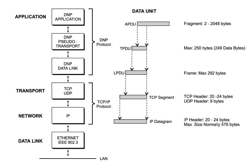
Physical layer. Defines the electrical interface. Serial or Ethernet. Nothing DNP3-specific here.
Data link layer. Handles frame delivery over one hop. It adds addressing, CRC checks, and optional confirmations. This layer does not know or care what data it carries.
Transport function. Splits a long application message into numbered segments and reassembles them at the far end. Each segment carries a FIR bit (first), a FIN bit (final), and a sequence number. A single-segment message has both FIR and FIN set.
Application layer. Where the real work happens. Function codes, object headers, point data, and the Internal Indications field all live here.
A full breakdown of how a message is built and torn down layer by layer is in the DNP3 message structure guide.
Inside a DNP3 frame
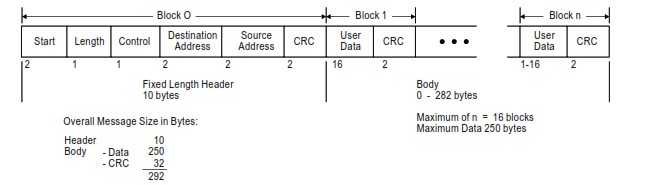
Every link layer frame opens with a fixed 10-octet header:
| Field | Size | What it does |
|---|---|---|
| START | 2 octets | Always 0x05 0x64. Frame sync. |
| LENGTH | 1 octet | Count of non-CRC octets after this field. Minimum 5, maximum 255. |
| CONTROL | 1 octet | Direction, primary/secondary flag, flow control bits, link function code. |
| DESTINATION | 2 octets | Address of the receiving device. |
| SOURCE | 2 octets | Address of the sending device. |
| CRC | 2 octets | Covers the eight octets above. |
After the header come data blocks. Each block holds up to 16 octets of user data followed by its own 2-octet CRC. That is why the maximum frame is 292 octets rather than a round number.
Two things trip people up here. First, LENGTH does not count CRC bytes, so the octet count you see on the wire is always larger than the LENGTH value. Second, the CONTROL octet’s FCB and FCV bits are used for duplicate detection on serial links, and mismatched FCB state is a classic cause of a link that resets over and over.
You can paste a captured frame into the online DNP3 frame decoder to see these fields broken out. For live traffic, the Wireshark DNP3 guide covers filters and dissector setup.
The object model
This is what separates DNP3 from register-based protocols. DNP3 does not ask for “40001.” It asks for an object group, a variation, and a point index.
Group says what kind of data. Group 1 is binary inputs. Group 30 is analog inputs. Group 20 is counters.
Variation says how that data is formatted. Group 30 variation 1 is a 32-bit analog input with flag. Variation 5 is a single-precision float with flag. Same point, different encoding on the wire.
Index says which point.
Because the format is negotiated per request, a master can ask an outstation for its analog inputs as 16-bit integers to save bandwidth on a slow radio link, then switch to floats when it moves to Ethernet. No remapping, no rewiring the database.
Variation 0 is a wildcard meaning “use the default variation.” Most integrity polls use variation 0 so the outstation picks its configured format.
The full breakdown of groups, variations, and how to read an object header is in DNP3 data objects, groups, and variations.
Static data, event data, and classes
Every point type exists in two forms.
Static data is the current value. Ask for it, get whatever the point reads right now.
Event data is a timestamped record that the value changed. Events queue up in the outstation buffer until the master collects them.
Each static group has a matching event group:
| Point type | Static group | Event group |
|---|---|---|
| Binary Input | 1 | 2 |
| Double-bit Binary Input | 3 | 4 |
| Binary Output Status | 10 | 11 |
| Binary Output Command | 12 | 13 |
| Counter | 20 | 22 |
| Frozen Counter | 21 | 23 |
| Analog Input | 30 | 32 |
| Frozen Analog Input | 31 | 33 |
| Analog Output Status | 40 | 42 |
| Analog Output Command | 41 | 43 |
| Data Set | 86 | 88 |
| Octet String | 110 | 111 |
| Virtual Terminal | 112 | 113 |
| Security Statistics | 121 | 122 |
Events are sorted into three classes. Class 1 is normally the highest priority, Class 3 the lowest, though nothing in the protocol forces that ranking — it is a configuration choice. Class 0 is not an event class at all. It means “all static data.”
Group 60 is the special group used to request class data. Group 60 variation 1 is Class 0, variation 2 is Class 1, variation 3 is Class 2, variation 4 is Class 3.
Authentication objects and security statistic events cannot be assigned to Class 0 or to no class. An outstation that receives an ASSIGN_CLASS request trying to do that returns a null response with the NO_FUNC_CODE_SUPPORT bit set.
More on how the classes behave in practice: DNP3 event classes explained.
DNP3 function codes
The application layer defines 34 function codes. Codes 0x00 through 0x21 are requests and confirmations. Codes 0x81 through 0x83 are responses. Everything else is reserved.
| Code | Name | Purpose |
|---|---|---|
| 0x00 | CONFIRM | Acknowledge receipt of an application fragment |
| 0x01 | READ | Return the data named by the objects in the request |
| 0x02 | WRITE | Store the data named by the objects in the request |
| 0x03 | SELECT | Arm output points, do not operate yet |
| 0x04 | OPERATE | Activate points armed by a prior SELECT |
| 0x05 | DIRECT_OPERATE | Operate immediately, no SELECT needed |
| 0x06 | DIRECT_OPERATE_NR | Same as 0x05, no response returned |
| 0x07 | IMMED_FREEZE | Copy point values to the freeze buffer |
| 0x08 | IMMED_FREEZE_NR | Same as 0x07, no response |
| 0x09 | FREEZE_CLEAR | Freeze, then clear the source points |
| 0x0A | FREEZE_CLEAR_NR | Same as 0x09, no response |
| 0x0B | FREEZE_AT_TIME | Freeze at a scheduled time or interval |
| 0x0C | FREEZE_AT_TIME_NR | Same as 0x0B, no response |
| 0x0D | COLD_RESTART | Full device restart |
| 0x0E | WARM_RESTART | Partial restart |
| 0x0F | INITIALIZE_DATA | Obsolete, retained for compatibility |
| 0x10 | INITIALIZE_APPL | Put the named application in a ready-to-run state |
| 0x11 | START_APPL | Start the named application |
| 0x12 | STOP_APPL | Stop the named application |
| 0x13 | SAVE_CONFIG | Deprecated |
| 0x14 | ENABLE_UNSOLICITED | Allow unsolicited reporting on named points |
| 0x15 | DISABLE_UNSOLICITED | Block unsolicited reporting on named points |
| 0x16 | ASSIGN_CLASS | Move points to a different class |
| 0x17 | DELAY_MEASURE | Measure channel propagation delay |
| 0x18 | RECORD_CURRENT_TIME | Timestamp on receipt, used for LAN time sync |
| 0x19 | OPEN_FILE | Open a file |
| 0x1A | CLOSE_FILE | Close a file |
| 0x1B | DELETE_FILE | Delete a file |
| 0x1C | GET_FILE_INFO | Return file information |
| 0x1D | AUTHENTICATE_FILE | Return an authentication key for file access |
| 0x1E | ABORT_FILE | Abort a file transfer |
| 0x1F | ACTIVATE_CONFIG | Activate a configuration or file |
| 0x20 | AUTHENTICATE_REQ | Secure authentication message |
| 0x21 | AUTH_REQ_NO_ACK | Secure authentication, no response |
| 0x81 | RESPONSE | Reply to a master request |
| 0x82 | UNSOLICITED_RESPONSE | Report sent without being asked |
| 0x83 | AUTHENTICATE_RESP | Secure authentication response |
In practice a running system uses maybe six of these. READ, WRITE, DIRECT_OPERATE, SELECT/OPERATE, ENABLE_UNSOLICITED, and CONFIRM cover most traffic. The rest show up during commissioning, firmware work, or file transfer.
The _NR suffix. It means “no response.” The outstation acts on the command but sends nothing back. Useful for broadcast commands, dangerous when you need confirmation that a breaker actually operated.
How a session actually runs
A typical master to outstation exchange follows this pattern.
- Link reset. The master resets the link layer to sync the FCB state.
- Integrity poll. A READ for Class 0, 1, 2, and 3. This pulls every static value plus any queued events, giving the master a complete picture.
- Time sync. If the outstation has set the NEED_TIME bit, the master writes the current time.
- Enable unsolicited. The master tells the outstation it may report on its own.
- Event polls. From here the master only asks for Classes 1, 2, and 3. It reads events, not full values.
- Periodic integrity poll. Every few minutes or hours, a full Class 0-3 read resynchronizes the database in case an event was lost.
That last step matters. Event buffers overflow. When they do, the outstation sets the EVENT_BUFFER_OVERFLOW bit, and the master needs an integrity poll to recover the true state.
Outstations can also push data without being asked. That is the unsolicited response, and it is what makes DNP3 efficient on low-bandwidth links. Instead of polling 200 RTUs every second, the master waits and the RTUs speak when something changes. See report by exception, background polls, and balanced communication for how to tune this.
Topology matters here too. DNP3 supports one master to one outstation, one master to many, many masters to one, and peer arrangements. The DNP3 system topology guide covers the tradeoffs.
Internal Indications
Every outstation response carries a two-octet Internal Indications field. It is the outstation telling the master about its own condition, and it is the first place to look when something is wrong.
| Bit | Name | Meaning |
|---|---|---|
| IIN1.0 | BROADCAST | A broadcast message was received |
| IIN1.1 | CLASS_1_EVENTS | Class 1 events are waiting |
| IIN1.2 | CLASS_2_EVENTS | Class 2 events are waiting |
| IIN1.3 | CLASS_3_EVENTS | Class 3 events are waiting |
| IIN1.4 | NEED_TIME | Time synchronization is required |
| IIN1.5 | LOCAL_CONTROL | One or more points are in local control mode |
| IIN1.6 | DEVICE_TROUBLE | A device-specific abnormal condition exists |
| IIN1.7 | DEVICE_RESTART | The outstation restarted |
| IIN2.0 | NO_FUNC_CODE_SUPPORT | Function code not supported |
| IIN2.1 | OBJECT_UNKNOWN | Requested operation not supported for those objects |
| IIN2.2 | PARAMETER_ERROR | A parameter error was detected |
| IIN2.3 | EVENT_BUFFER_OVERFLOW | Buffer overflowed, at least one event was lost |
| IIN2.4 | ALREADY_EXECUTING | The requested operation is already running |
| IIN2.5 | CONFIG_CORRUPT | The outstation detected corrupt configuration |
| IIN2.6 | RESERVED_2 | Always 0 |
| IIN2.7 | RESERVED_1 | Always 0 |
IIN1.7 does not clear itself. The master has to write it back to zero. An outstation stuck with DEVICE_RESTART set usually means the master never sent that write, not that the device keeps rebooting.
IIN1.5 (LOCAL_CONTROL) is the one that catches people during commissioning. A control command that returns success but changes nothing is often a point left in local mode at the panel.
Full bit-by-bit troubleshooting: DNP3 Internal Indications guide.
Conformance levels
Not every device implements the whole protocol. A relay does not need file transfer. A feeder controller does not need data sets.
The standard defines subset levels — commonly written L1 through L4 — that specify a minimum set of objects, variations, and function codes. A device claims a level, and any master supporting that level should interoperate with it.
- Level 1 — the smallest useful set. Simple field devices.
- Level 2 — adds analog output control and more variations.
- Level 3 — adds unsolicited reporting and broader object support.
- Level 4 — the fullest set, including floating point and data sets.
Two devices at the same level are not automatically interoperable, because a device can support anything above its claimed level as an extra. That is what the device profile is for.
Details on what each level requires: DNP3 implementation levels L1 to L4.
Serial and TCP/IP
DNP3 was designed for serial links, and the link layer still reflects that. CRC on every 16 bytes, retries, confirmations — all of it assumes a noisy channel.
Over Ethernet, the same frames get wrapped in TCP or UDP on port 20000. Outstations must listen on 20000. Masters must be able to connect to it. Both sides may allow a configurable port, but 20000 has to be available as an option.
The link layer confirmations become redundant over TCP, since TCP already guarantees delivery. Most implementations turn link confirms off on Ethernet to cut round trips. Leaving them on is a common cause of sluggish polling on an otherwise fast network.
UDP is allowed and is the only option for broadcast. Broadcast destination addresses are 0xFFFD, 0xFFFE, and 0xFFFF.
More on the network side: DNP3 port 20000.
Security
The original protocol had none. No authentication, no encryption, everything in the clear. That was acceptable on a leased line in 1993 and is not acceptable on a routed network today.
DNP3 Secure Authentication adds message authentication using shared or public keys. It is built on IEC/TS 62351-5, and the version in IEEE 1815-2012 is SAv5. The scheme is challenge-response: the receiver challenges a critical request, the sender replies with a MAC computed over the message.
Because challenge-response doubles the message count, DNP3 also defines Aggressive Mode, where the MAC travels inside the original message and no separate challenge is needed. Aggressive Mode is optional in IEC/TS 62351-5, but every DNP3 implementation of secure authentication is required to support it.
SAv5 authenticates. It does not encrypt. If you need confidentiality, you wrap DNP3 in TLS.
SAv6 is a later DNP Users Group specification, not part of IEEE 1815-2012. It simplifies key management and drops some SAv5 complexity that hurt adoption.
Deeper coverage: DNP3 Secure Authentication and DNP3 SAv6.
The Device Profile Document
Every conforming device ships a Device Profile Document. It is a standardized form listing exactly which objects, variations, function codes, and qualifiers the device supports, plus timing parameters and defaults.
When two DNP3 devices will not talk, the answer is almost always in the two profiles. One asks for group 30 variation 5 and the other only supports variations 1 through 4. The link is fine. The object support is not.
Ask for the profile before you buy, not after the outstation is on a pole.
DNP3 compared to Modbus and IEC 60870-5-104
| DNP3 | Modbus | IEC 60870-5-104 | |
|---|---|---|---|
| Data model | Objects with groups and variations | Registers and coils | Information objects with type IDs |
| Timestamps | Built in, per event | None | Built in |
| Event buffering | Yes, class-based | No | Yes |
| Unsolicited reporting | Yes | No | Yes |
| Quality flags | Yes | No | Yes |
| Default TCP port | 20000 | 502 | 2404 |
| Address space | 65520 | 247 serial nodes | Configurable |
| Primary region | North America | Global | Europe, Asia |
The short version: Modbus is simpler and enough for a local device on a panel. DNP3 and IEC 104 are telemetry protocols built for wide-area links where you need timestamps, quality flags, and event history. Choosing between DNP3 and IEC 104 is usually about which region you are in and what your control center already speaks.
For the feature-level view, see top DNP3 features for SCADA systems.
Frequently asked questions
Is DNP3 the same as IEEE 1815?
Yes. IEEE 1815 is the formal standard number for DNP3. The current edition is IEEE Std 1815-2012.
What port does DNP3 use?
TCP and UDP port 20000. Outstations must listen on it. Masters must be able to reach it.
Is DNP3 an open protocol?
The specification is in the public domain and anyone can implement it. The IEEE 1815 document itself is a paid standard, and full conformance testing runs through the DNP Users Group.
How many devices can DNP3 address?
65520 individual addresses, numbered 0 to 65519. The range 0xFFF0 to 0xFFFF is reserved, and 0xFFFD to 0xFFFF are broadcast.
What is the difference between static and event data?
Static data is the value right now. Event data is a timestamped record that the value changed, held in a buffer until the master collects it.
Why does my outstation keep reporting DEVICE_RESTART?
IIN1.7 stays set until a master explicitly writes it back to zero. If the master never sends that write, the bit persists even though the device rebooted only once.
Does DNP3 encrypt traffic?
Not by itself. Secure Authentication verifies who sent a message and that it was not altered, but the payload stays readable. Add TLS if you need confidentiality.
Can DNP3 and Modbus run on the same device?
Yes. Most RTUs and gateways run several protocol stacks at once, often speaking Modbus to local equipment and DNP3 upstream to the control center.
What is a Device Profile Document?
A standardized form each conforming device publishes, listing exactly which objects, variations, function codes, and parameters it supports. It is the first thing to check when two devices will not interoperate.