
CODESYS is the runtime that powers a large chunk of the industrial PLC market — WAGO, Phoenix Contact, ABB, Delta, Eaton, Bosch Rexroth, Turck, and many more all use CODESYS underneath their own branded engineering software. The good news for anyone working with Modbus TCP on these platforms: CODESYS has native Modbus TCP support built in. No third-party modules, no socket messaging AOIs, no external gateways. Just add the device, configure the channels, and map the variables.
This article walks through configuring Modbus TCP on CODESYS 3.5 PLCs — both as a client (master) polling remote devices, and as a server (slave) exposing PLC variables to external systems. Vendor-specific notes cover the small differences you will encounter with WAGO, Phoenix Contact, Delta, ABB, and other CODESYS-based brands.
Table of Contents
Which PLCs use CODESYS?
Before we get into configuration: CODESYS is a runtime environment, not a brand. Many industrial PLC vendors ship products with CODESYS underneath, often rebranded as their own engineering software.
| Vendor | Engineering software | CODESYS-based? |
|---|---|---|
| WAGO | e!COCKPIT, CODESYS 3.5 | ✅ Yes |
| Phoenix Contact | PLCnext Engineer | ⚠️ Different runtime (PLCnext Runtime; IEC 61131-3 but not CODESYS) |
| ABB | Automation Builder | ✅ Yes (CODESYS 3.5) |
| Delta | ISPSoft, DIAStudio | ✅ Yes (AH/AX series) |
| Eaton | XSoft-CODESYS | ✅ Yes (CODESYS 3.5) |
| Bosch Rexroth | IndraWorks | ✅ Yes (CODESYS 3.5) |
| Turck | CODESYS 3.5 | ✅ Yes |
| Schneider Electric | EcoStruxure Machine Expert | ✅ Yes (built on CODESYS technology, formerly SoMachine) |
| Beckhoff | TwinCAT | ❌ IEC 61131-3 platform but does not use the CODESYS runtime |
| Siemens | TIA Portal | ❌ Different runtime |
| Allen-Bradley | Studio 5000 | ❌ Different runtime |
If you are on a CODESYS-based platform, the configuration steps in this article apply with minor UI variations. If you are on a non-CODESYS platform, see our other PLC-specific Modbus TCP articles instead.
CODESYS native Modbus TCP support
CODESYS 3.5 supports Modbus TCP as a first-class protocol in two roles:
Modbus TCP Master (Client) — Your PLC initiates requests to remote Modbus TCP servers. Use this when your PLC needs to poll data from Modbus-enabled devices (drives, meters, sensors, gateways).
Modbus TCP Slave (Server) — Your PLC accepts incoming requests from remote Modbus TCP clients. Use this when a SCADA system, HMI, or another PLC needs to read/write your PLC’s variables using Modbus TCP.
Both roles can run on the same PLC simultaneously. The PLC can be a client to some devices and a server to others on the same Ethernet interface.
CODESYS uses “Master/Slave” in its device tree labels even in modern versions, matching the traditional Modbus vocabulary. For the general terminology discussion, see our Modbus Client-Server vs Master-Slave Terminology article.
Prerequisites
Before configuring Modbus TCP on a CODESYS PLC:
- CODESYS 3.5 (or vendor-branded equivalent) installed
- A CODESYS-based PLC with an Ethernet port
- The PLC’s device description package installed in CODESYS
- Network configuration on the PLC’s Ethernet interface (IP address, subnet, gateway)
- Firewall rules allowing TCP port 502 (both directions if using client and server roles)
Verify the Ethernet interface is enabled and configured before starting. The PLC’s own IP address must be set correctly, or Modbus TCP cannot function.
Modbus TCP Master (Client) configuration
The most common use case: your CODESYS PLC polls one or more remote Modbus TCP devices.
Step 1: Add the Ethernet adapter
In the CODESYS Device tree:
- Right-click the PLC device → Add Device
- Select Fieldbuses → Ethernet Adapter → Ethernet
- Click Add Device
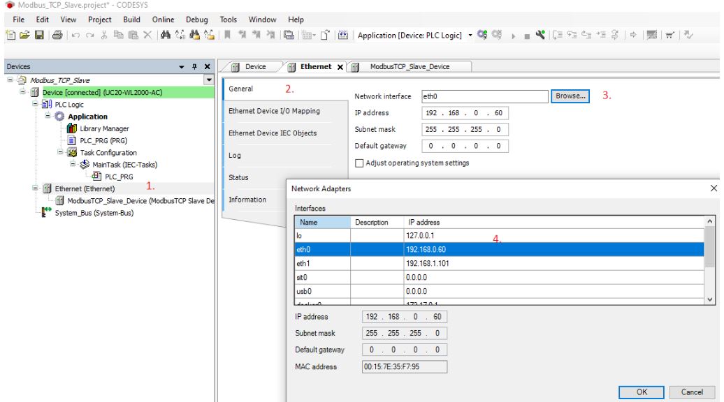
An “Ethernet” node appears under the PLC in the device tree. Double-click it and confirm the network interface, IP address, and subnet mask are correct for your PLC.
Step 2: Add the Modbus TCP Master
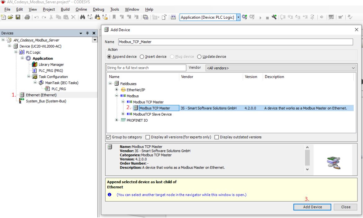
- Right-click the newly added Ethernet node → Add Device
- Select Fieldbuses → Modbus → Modbus TCP Master
- Click Add Device
A “Modbus_TCP_Master” node appears under Ethernet. Double-click to configure:
- Response Timeout — how long the master waits for a response before flagging a timeout (typical: 1000 ms)
- Socket Timeout — TCP connection timeout (typical: 5000 ms)
- Auto-reconnect — enable to retry automatically after connection loss
Step 3: Add remote Modbus TCP slaves
For each remote Modbus TCP device you need to poll:
- Right-click the Modbus_TCP_Master node → Add Device
- Select Fieldbuses → Modbus → Modbus TCP Slave
- Name the slave meaningfully (e.g., “Flow_Meter_1”, not “Modbus_TCP_Slave”)
- Click Add Device
Double-click the slave to configure:
- Slave IP Address — the remote device’s IP (e.g., 192.168.1.50)
- Slave Port — 502 (default Modbus TCP port)
- Unit ID — the Modbus Unit ID of the target device (see our Modbus Unit Identifier article for guidance)
- Response Timeout — override the master default if needed
Step 4: Define Modbus channels
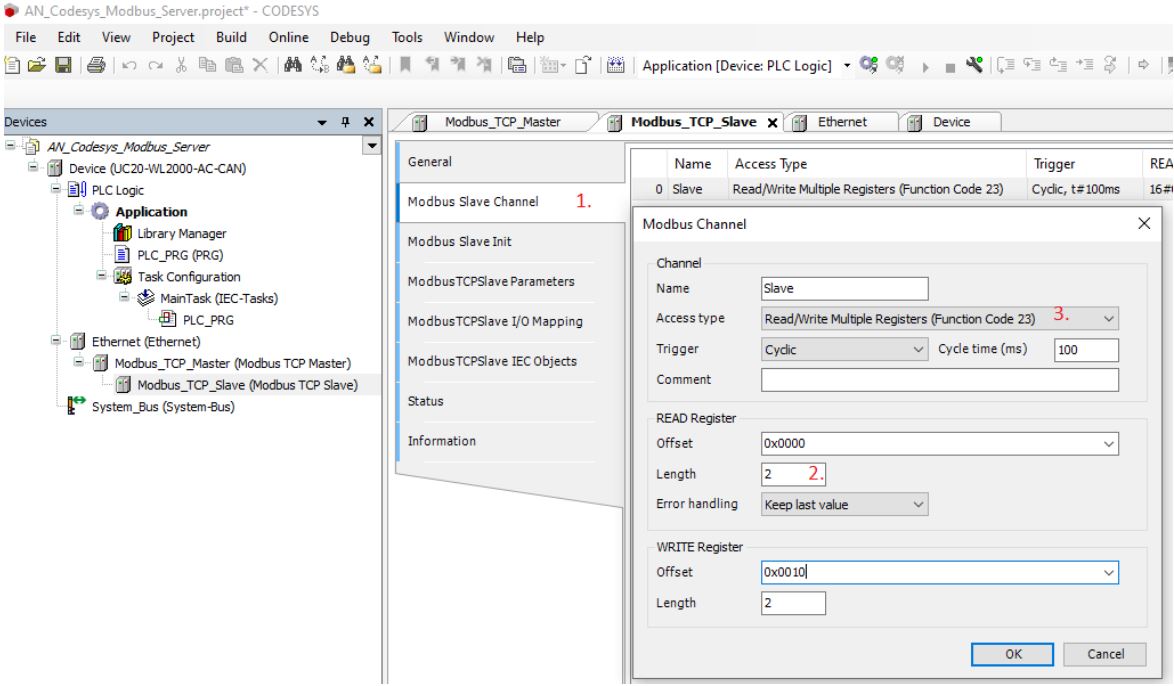
Each channel is one Modbus request that the master will send periodically. To add channels:
- Double-click the slave → Modbus Slave Channel tab
- Click Add Channel
- Configure:
- Name — meaningful (e.g., “Read_Flow_Registers”)
- Access Type — the Modbus function code to use. Common options: Read Holding Registers (FC 3), Read Input Registers (FC 4), Write Single Register (FC 6), Write Multiple Registers (FC 16), and Read/Write Multiple Registers (FC 23) for simultaneous read and write in one transaction
- Trigger — Cyclic (with cycle time) or Rising Edge (application-triggered)
- Cycle Time — how often to send this request (e.g., 100 ms)
- READ Register section (for read/read-write function codes):
- Offset — starting register address (e.g., 0x0000)
- Length — number of registers to read
- Error handling — what to do when the read fails. “Keep last value” retains the previous data; “Set to zero” clears it
- WRITE Register section (for write/read-write function codes):
- Offset — starting register address for writing
- Length — number of registers to write
- Comment — describe what this channel does
Add one channel per Modbus operation you need. Common patterns:
- One “Read Holding Registers” channel for process data (fast cycle, e.g., 100 ms)
- One “Read Input Registers” channel for status data (slower cycle, e.g., 1000 ms)
- One “Write Single Register” or “Write Multiple Registers” channel triggered by application logic
Step 5: Map channel data to PLC variables
The channel data becomes accessible in your PLC program through the Modbus Slave Channel I/O mapping:
- Double-click the slave → ModbusTCPSlave I/O Mapping tab
- Assign a variable name to each channel’s data
- Choose whether the variable is mapped by name (via GVL) or by absolute address
Example mapping:
| Channel Data | Variable |
|---|---|
| Read_Flow_Registers.Data[0] | Flow_Meter_1.Flow_Rate_Reg1 |
| Read_Flow_Registers.Data[1] | Flow_Meter_1.Flow_Rate_Reg2 |
| Read_Flow_Registers.Data[2] | Flow_Meter_1.Total_Volume_Reg1 |
Once mapped, your ladder logic, ST, or FBD code can read these variables directly.
Step 6: Handle 32-bit values
Modbus registers are 16 bits, but many devices pack 32-bit floats or integers across two consecutive registers. CODESYS and Modbus devices may use different byte and word orderings, so you often need conversion logic.
Simple example — combining two 16-bit registers into a 32-bit REAL. Important: TO_REAL(DWORD) in CODESYS performs a numeric conversion (integer value → floating-point equivalent), not a bit-level reinterpretation of the IEEE 754 representation. To reinterpret the raw 32 bits as a float, use a UNION (portable across CODESYS versions) or the appropriate reinterpret function for your runtime:
// Portable UNION-based reinterpretation
TYPE U_DwordReal :
UNION
    dw : DWORD;
    r  : REAL;
END_UNION
END_TYPE

FUNCTION ModbusToReal : REAL
VAR_INPUT
    High_Word : WORD;
    Low_Word  : WORD;
END_VAR
VAR
    u : U_DwordReal;
END_VAR

// Combine the two 16-bit registers into a 32-bit DWORD (ABCD byte order)
u.dw := SHL(TO_DWORD(High_Word), 16) OR TO_DWORD(Low_Word);

// Reinterpret the bit pattern as an IEEE 754 REAL
ModbusToReal := u.r;
For CDAB (word-swapped) devices, swap the two register inputs before combining. For BADC and DCBA, you also need to swap the bytes within each word before combining.
Some CODESYS runtimes also provide DWORD_TO_REAL or SysMem.MemCpy as alternatives to a UNION, but the UNION approach works reliably across versions.
For a full breakdown of the four possible byte/word arrangements (ABCD, CDAB, BADC, DCBA), see our Modbus Byte Order and Word Order article. Every CODESYS Modbus integration touches this problem eventually.
Step 7: Download and test
- Save the project
- Login to the PLC
- Download the program
- Set the PLC to Run mode
- Verify Modbus TCP traffic — see the Testing section below
CODESYS license note: On many CODESYS runtimes, the Modbus TCP device icon in the device tree indicates licensing status. An orange icon typically indicates a licensing issue or demo mode, meaning the Modbus TCP functionality may run with time-limited operation. A green icon typically confirms the license is active. Behavior varies by vendor runtime — check your PLC’s documentation for the exact indicator convention. Verify licensing before deploying to production.
Modbus TCP Slave (Server) configuration
Use this role when external systems (SCADA, HMI, other PLCs) need to read or write your CODESYS PLC’s variables using Modbus TCP.
Step 1: Add the Ethernet adapter
Same as the Master configuration. If you already have an Ethernet node in your device tree (from a Master setup), reuse it.
Note on IP addressing: when connecting a CODESYS Master and a CODESYS Slave on the same network, both PLCs must have IP addresses in the same subnet but with different individual IP addresses. For example, Master at 192.168.0.50 and Slave at 192.168.0.60, both with subnet mask 255.255.255.0.
Step 2: Add the Modbus TCP Slave Device
- Right-click Ethernet → Add Device
- Select Fieldbuses → Modbus → Modbus TCP Slave Device
- Click Add Device
Note the naming: Modbus TCP Slave Device (added under Ethernet directly) is the server role — your PLC accepts incoming Modbus TCP requests. In contrast, the Modbus TCP Slave (added under a Master, described earlier) refers to a remote device your PLC polls.
Quick reference for what to add and where:
| You add… | Meaning |
|---|---|
| Modbus TCP Master | Your PLC polls remote devices (PLC = client) |
| Modbus TCP Slave (under Master) | A specific remote device your Master will poll |
| Modbus TCP Slave Device (under Ethernet) | Your PLC acts as a server accepting external requests |
Confusingly named, but the CODESYS device tree icons make the distinction clear once you see them.
Step 3: Configure the slave device
Double-click Modbus_TCP_Slave_Device. The General tab exposes the full set of slave parameters:
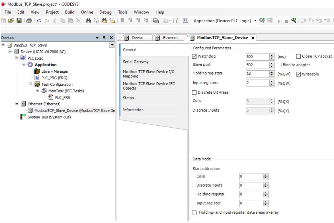
Configured Parameters:
- Watchdog — the maximum time the slave will wait between Modbus messages before considering the connection stale (typical: 500 ms). If no message arrives within this window, the slave can close the connection or flag it as inactive, depending on the runtime implementation. Set to 0 to disable the watchdog.
- Slave Port — TCP port the slave listens on (default: 502)
- Bind to adapter — restrict listening to a specific network adapter, useful when the PLC has multiple Ethernet interfaces
- Close TCP socket — automatically close the TCP socket when the watchdog triggers instead of only flagging the connection
- Holding Registers — number of holding registers to expose
- Writeable — controls whether external clients can write to the holding registers, or only read them
- Input Registers — number of input registers to expose (read-only by definition)
- Discrete Bit Areas — enable bit-level access via coils and discrete inputs
- Coils — number of coils to expose (read/write bits)
- Discrete Inputs — number of discrete inputs to expose (read-only bits)
Data Model (below the Configured Parameters):
- Start addresses for Coils, Discrete Inputs, Holding Registers, and Input Registers — the starting Modbus address offset for each register type in the CODESYS memory model. Default is 0 for each. Change these if your external Modbus client expects a different address layout.
- Holding- and input register data areas overlay — when enabled, the holding register and input register memory areas share the same underlying storage. Reads from an input register return the same value as reads from the corresponding holding register. Useful when you want to expose the same data as both read-only and read-write registers.
For each register type, CODESYS reserves a memory area that external Modbus TCP clients can access.
Step 4: Map PLC variables to the exposed registers
- Double-click the slave device → ModbusTCPSlave_Device I/O Mapping tab
- Assign your PLC variables to the register memory areas
Example mapping:
| Modbus Register | PLC Variable |
|---|---|
| Holding Register 0 | Setpoint.Temperature |
| Holding Register 1 | Setpoint.Pressure |
| Holding Register 2 | Setpoint.Flow |
| Input Register 0 | Actual.Temperature |
| Input Register 1 | Actual.Pressure |
| Coil 0 | Command.Start |
| Coil 1 | Command.Stop |
External Modbus TCP clients now see these variables through standard Modbus function codes (0x03 to read holding registers, 0x06 to write, etc.).
Step 5: Download and test with an external Modbus client
Use a Modbus TCP master tool (OpenModScan, ModbusMechanic — see our Best Free Modbus Software article) to connect to your PLC’s IP address on TCP port 502 with the configured Unit ID. Read holding registers 0-2 to see the setpoint variables.
Vendor-specific notes
CODESYS is common across vendors but each brand adds its own flavor.
WAGO PFC / e!COCKPIT
WAGO’s e!COCKPIT is CODESYS 3.5 with WAGO libraries and device profiles. Modbus TCP configuration follows the standard CODESYS approach described above. Notes:
- The WagoAppPlcModbus library provides alternative function-block-based Modbus TCP if you prefer FB-based programming over the device tree approach
- WAGO 750 series controllers have specific IP configuration steps via WBM (Web-Based Management)
- Some older WAGO controllers use CODESYS V2 — the configuration UI is different but the Modbus TCP concepts are similar
Phoenix Contact PLCnext
Phoenix Contact’s PLCnext platform uses PLCnext Runtime, not CODESYS Runtime. Although PLCnext Engineer looks similar to a CODESYS environment and supports IEC 61131-3 languages, the underlying runtime and Modbus configuration workflow are different from standard CODESYS projects. Notes:
- The Modbus configuration in PLCnext Engineer is not the CODESYS Device Tree described above — Phoenix Contact provides its own function block libraries and configuration screens
- If you have a Phoenix Contact ILC controller (not PLCnext), you use PC Worx, which is also not CODESYS-based
- Do not assume the CODESYS steps in this article apply directly to PLCnext — consult Phoenix Contact documentation for the equivalent workflow
ABB Automation Builder / AC500
ABB’s Automation Builder for AC500 PLCs is CODESYS 3.5. Notes:
- The AC500 CM597-ETH or ETH1 port on the PM5xx CPU is used for Modbus TCP
- Device tree approach works — add Ethernet, then Modbus TCP Master or Slave Device
- ABB’s IEC 61131-3 libraries include additional Modbus function blocks if you prefer library-based configuration
- On AC500 V3 CPUs, the specific Modbus objects and features available depend on the CPU firmware version and Automation Builder version — check the release notes for the combination you are using
Delta AS/AH/AX Series
Delta’s DIAStudio (formerly ISPSoft) is CODESYS-based for the AH and AX series. Notes:
- Delta has its own Modbus TCP configuration wizard for simple cases
- The advanced CODESYS device tree approach also works
- Delta drives on the same network can be polled via Modbus TCP once you know their Unit IDs and register maps
Eaton XSoft-CODESYS
Standard CODESYS 3.5. Follow the configuration steps as-is. Eaton’s XC and XV series controllers work with the standard CODESYS Modbus TCP approach.
Bosch Rexroth IndraWorks
IndraWorks is Rexroth’s engineering software for XM and Motion Logic controllers, based on CODESYS 3.5. Configuration follows the standard CODESYS approach.
Schneider EcoStruxure Machine Expert
EcoStruxure Machine Expert (formerly SoMachine) is used for Schneider’s Modicon M241/M251/M262/M258 controllers. It is built on CODESYS technology with Schneider extensions. Standard CODESYS Modbus TCP configuration applies. Note: Schneider’s larger Modicon M340/M580 controllers use EcoStruxure Control Expert (Unity Pro), which is NOT CODESYS-based — a separate configuration path entirely.
Testing your CODESYS Modbus TCP setup
After downloading the project to the PLC, verify Modbus TCP is working.
Test 1: Ping the PLC
From a laptop on the same network, ping the PLC’s IP address. If ping fails, fix network connectivity before troubleshooting Modbus.
Test 2: Connect with an external Modbus master
Use OpenModScan, ModbusMechanic, or another free Modbus master tool to connect to your PLC’s IP on port 502. Read a holding register you configured. If you can read data successfully, the Modbus TCP Slave Device (server) is working.
Test 3: Watch the Modbus channel status in CODESYS
For the Modbus TCP Master role, CODESYS shows channel status in the device tree when connected to a running PLC:
- Green icon = communication OK
- Red icon = communication error
- Right-click the channel → Diagnostics for error details
Common status errors:
- Timeout — target device not responding
- Connection refused — target device not accepting connections
- Frame error — usually indicates transport issues
Test 4: Capture with Wireshark
If problems persist, capture TCP port 502 traffic between the CODESYS PLC and the target device with Wireshark. See our Wireshark for Modbus TCP article for setup. Wireshark shows the actual bytes exchanged and helps diagnose Unit ID mismatches, byte order issues, or protocol errors.
Common pitfalls
Real CODESYS Modbus TCP integrations hit these regularly.
1. Ethernet interface not enabled
Symptom: Modbus TCP nodes in the device tree show errors immediately after download. Fix: verify the PLC’s Ethernet interface is enabled and has a valid IP address. Check the PLC’s web interface or vendor-specific configuration tool.
2. Wrong CODESYS version library
Symptom: Modbus TCP options do not appear in the device tree, or library errors appear. Fix: install the Modbus TCP device support package matching your CODESYS 3.5 version. Some vendors ship their own version; verify you have the right library for your PLC.
3. Firewall blocking port 502
Symptom: TCP connection fails or times out. Fix: on some CODESYS runtime implementations, an internal firewall blocks port 502 by default. Enable Modbus TCP in the PLC’s security or firewall settings. When testing with CODESYS Control Win (simulation on a Windows PC), Windows Firewall is often the culprit — allow the CODESYS runtime process or TCP port 502 through Windows Defender Firewall.
4. Unit ID mismatch
Symptom: TCP connects but Modbus requests time out or return exceptions. Fix: match the Unit ID configured in CODESYS to what the target device expects. See our Modbus Unit Identifier article for guidance.
5. Byte order issues on 32-bit values
Symptom: register data reads correctly for INT16 but 32-bit floats and DINTs are garbage. Fix: implement byte-swap or word-swap logic in your ST/FBD code. See our Modbus Byte Order and Word Order article.
6. Cycle time too aggressive for the target device
Symptom: some responses missed, “Slave Device Busy” exceptions, timeouts under load. Fix: reduce the channel cycle time. Test the target device’s maximum sustained response rate with a Modbus master tool before setting the CODESYS cycle time.
7. Modbus TCP Slave vs Modbus TCP Slave Device confusion
Symptom: added the wrong device type for what you need. Fix: Modbus TCP Slave (under Master) = a remote device you poll. Modbus TCP Slave Device (under Ethernet) = your PLC acting as a slave/server. Both exist in the CODESYS device tree with similar names.
8. Variable mapping missing
Symptom: channels exist and communication succeeds, but variables in your program show zero. Fix: verify the I/O Mapping tab of each channel — every relevant data element must be mapped to a program variable.
9. Reserved memory areas too small
Symptom: mapping variables to registers beyond the configured range fails silently. Fix: increase the number of holding registers, input registers, coils, or discrete inputs in the slave device configuration.
10. Non-CODESYS vendor deviations
Symptom: standard CODESYS approach does not work despite the vendor claiming CODESYS compatibility. Fix: check whether the vendor uses an older CODESYS V2 or a proprietary variant. Some vendors override the standard Modbus TCP configuration with their own extensions.
Common questions
Does CODESYS support Modbus TCP natively?
Yes. CODESYS 3.5 includes native Modbus TCP support as a first-class fieldbus protocol. You configure it through the device tree: add an Ethernet adapter, then add either a Modbus TCP Master (for polling remote devices) or a Modbus TCP Slave Device (for exposing PLC variables to external systems). No third-party modules or add-on libraries are required.
Which PLCs use CODESYS runtime?
Many industrial PLC brands use CODESYS underneath their engineering software: WAGO (e!COCKPIT), Phoenix Contact (PLCnext Engineer), ABB (Automation Builder for AC500), Delta (DIAStudio for AH/AX series), Eaton (XSoft-CODESYS), Bosch Rexroth (IndraWorks), Turck, and Schneider Electric (EcoStruxure Machine Expert for M241/M251/M262/M258). Non-CODESYS brands include Siemens (TIA Portal), Allen-Bradley (Studio 5000), and Beckhoff (TwinCAT).
What is the difference between Modbus TCP Slave and Modbus TCP Slave Device in CODESYS?
Modbus TCP Slave is added under a Modbus TCP Master node — it represents a remote device that your PLC will poll (a client-to-server relationship where your PLC is the client). Modbus TCP Slave Device is added directly under the Ethernet adapter — it makes your PLC act as a Modbus TCP server, accepting requests from external Modbus clients. The naming is confusingly similar; use the icons in the device tree to distinguish them.
Can a CODESYS PLC act as both Modbus TCP master and slave at the same time?
Yes. You can add a Modbus TCP Master (with remote slaves under it) and a Modbus TCP Slave Device to the same Ethernet adapter in the CODESYS device tree. The PLC will simultaneously poll remote devices as a client and respond to incoming requests as a server. Both roles share the same Ethernet interface and IP address; the Slave Device listens on TCP port 502 while the Master initiates outbound connections to remote devices.
Why does my CODESYS Modbus TCP data show wrong values for 32-bit numbers?
Almost always a byte or word order issue. Modbus registers are 16 bits, so 32-bit floats and DINTs span two consecutive registers. Different Modbus devices use different byte and word orderings (ABCD, CDAB, BADC, or DCBA). CODESYS reads the two 16-bit registers as-is; you need to combine them in the correct order in your PLC code. Test with a known value first — 1.0 as IEEE 754 float is 0x3F800000.