Industrial Ethernet networks are expected to operate continuously, even when cables fail or devices are powered off. In many automation environments, a short communication interruption can stop production, affect safety, or cause loss of control. To address this requirement, several standardized redundancy protocols have been developed. One of them is the Ring-based Redundancy Protocol (RRP).
RRP is defined in IEC 62439-7 and is designed for Ethernet networks built in a ring topology. It provides fast and deterministic recovery after a single failure while keeping the network architecture simple and cost-effective. This article explains RRP in detail: how it works, how failures are detected, how recovery is achieved, and where the protocol is typically used.
Table of Contents
What Is Ring-based Redundancy Protocol (RRP)?
Ring-based Redundancy Protocol (RRP) is an Ethernet redundancy protocol where network devices are connected in a closed ring and cooperate to maintain communication when a failure occurs.
Key characteristics of RRP:
- Uses standard Ethernet (IEEE 802.3)
- Operates on a physical ring topology
- Redundancy logic is implemented in end devices
- No frame duplication during normal operation
- Recovery time in the millisecond range
RRP is standardized in IEC 62439-7, which focuses on ring-based redundancy mechanisms for industrial networks.
Why Ring-based Redundancy Is Used in Industrial Networks
Industrial networks differ from office IT networks in several ways:
- Traffic must be predictable
- Delays must be bounded
- Recovery must be automatic
- Configuration should be simple
A ring topology is attractive because:
- It requires fewer cables than full mesh designs
- Each device only needs two Ethernet ports
- The physical layout is easy to extend
Without a redundancy protocol, however, a ring would create Ethernet loops. RRP solves this by logically breaking the ring during normal operation and reconnecting it automatically after a failure.
Position of RRP in the IEC 62439 Family
IEC 62439 defines multiple redundancy solutions:
- PRP (Parallel Redundancy Protocol) – zero recovery time using two independent networks
- HSR (High-availability Seamless Redundancy) – zero recovery time using frame duplication in a ring
- RRP (Ring-based Redundancy Protocol) – fast recovery with no frame duplication
RRP is typically chosen when:
- Zero-time recovery is not mandatory
- Millisecond recovery is acceptable
- Network simplicity and cost are important
RRP Network Topology Explained
An RRP network is built as a physical ring. Each device in the ring has:
- Two Ethernet ports (R-ports)
- An internal switching function
- RRP protocol logic
Device A → Device B → Device C → Device D
     ↑________________________________↓
Under normal conditions, the protocol ensures that the ring behaves like a logical line, avoiding loops while keeping a backup path available.
RRP Device Roles
Ring-based Redundancy Protocol defines two main types of devices inside an RRP network: the Normal Device (ND) and the Gateway Device (GWD). Although both participate in the ring, their internal structure and role in the network are different.
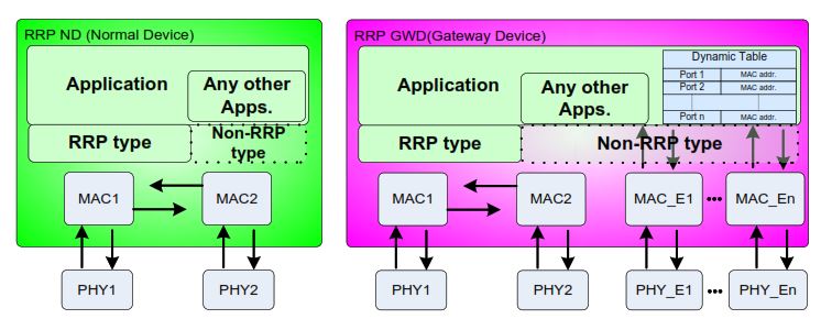
RRP Normal Device (ND)
An RRP Normal Device (ND) is used only inside the RRP ring and does not connect external Ethernet networks.
At the top of the device, the Application layer and other applications exchange data with the network through the RRP communication stack. All communication that leaves or enters the device through the ring is handled as RRP-type traffic.
Below the application layer, the device contains:
- Two MAC entities (MAC1 and MAC2)
- Each MAC is directly connected to one physical Ethernet interface
- Two PHYs (PHY1 and PHY2) corresponding to the two ring ports
The two MACs are interconnected internally, allowing frames to be forwarded from one ring port to the other under the control of the RRP forwarding logic.
Key characteristics of an RRP Normal Device:
- Both Ethernet ports are RRP ports
- The device participates fully in ring forwarding and redundancy control
- There are no non-RRP ports
- No dynamic MAC learning toward external networks is required
The Normal Device forwards frames only within the RRP ring and relies on the protocol to decide whether frames are forwarded, blocked, or accepted locally.
RRP Gateway Device (GWD)
An RRP Gateway Device (GWD) connects the RRP ring to non-RRP Ethernet networks. It combines RRP functionality with standard Ethernet switching behavior.
At the application level, the device runs normal applications and may exchange data with both:
- RRP-type networks (the ring)
- Non-RRP Ethernet networks
Internally, the Gateway Device contains:
- Two MAC entities (MAC1 and MAC2) connected to the RRP ring ports
- Additional MAC entities (MAC_E1 … MAC_En) connected to non-RRP Ethernet ports
- Corresponding PHYs (PHY1, PHY2, PHY_E1 … PHY_En)
Unlike a Normal Device, the Gateway Device maintains a dynamic MAC address table. This table is used to:
- Learn MAC addresses from non-RRP ports
- Decide where to forward frames between RRP and non-RRP networks
- Prevent unnecessary flooding
Key characteristics of an RRP Gateway Device:
- Two ports are RRP ports and participate in ring redundancy
- One or more ports are non-RRP Ethernet ports
- Dynamic MAC learning is enabled for non-RRP traffic
- Acts as the interface between the RRP ring and external networks
The Gateway Device ensures that traffic entering or leaving the RRP ring is forwarded correctly while preserving the redundancy behavior defined by the protocol.
This clear separation of roles allows RRP networks to remain deterministic and loop-free while still supporting integration with standard Ethernet infrastructure.
Ring Network Manager (RNM) and Line Network Manager (LNM) Operation
To prevent Ethernet loops and ensure fast recovery from failures, Ring-based Redundancy Protocol (RRP) uses two different management roles depending on the network state:
- Ring Network Managers (RNMs) during normal ring operation
- Line Network Managers (LNMs) during fault conditions
These roles are automatically assigned and removed by the protocol without manual configuration.
Unique Identifier (UID)
Each RRP device is assigned a Unique Identifier (UID).
The UID is derived from:
- The device address
- The device MAC address
This combination guarantees that every device in the ring has a unique and comparable identifier, which is essential for manager election and deterministic behavior.
Ring Network Manager (RNM) Election
To avoid Ethernet loops in a healthy ring topology, RRP automatically elects Ring Network Managers (RNMs). These managers control frame forwarding so that the physical ring behaves as a logical line during normal operation.
RNM election process
The election process is fully automatic and works as follows:
- Exchange of control messages
All RRP devices periodically exchange network control messages containing their UID and current status. - Learning of ring topology
Through these messages, each device learns the UIDs of all other devices and builds a consistent view of the ring. - Selection of the Primary Ring Network Manager (RNMP)
The device with the highest UID is automatically selected as the Primary Ring Network Manager (RNMP). - Selection of the Secondary Ring Network Manager (RNMS)
One device adjacent to the RNMP is selected as the Secondary Ring Network Manager (RNMS).
The RNMS supports topology control and provides redundancy if the RNMP fails. - Activation of forwarding control
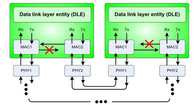
During normal operation, the RNMP and RNMS block forwarding between MAC1 and MAC2 on opposite sides of the ring.
This breaks the loop logically while keeping the backup path available.
As shown in the RNM forwarding diagram, one RNM blocks forwarding in one direction and the other RNM blocks forwarding in the opposite direction. The result is a loop-free logical line built on a physical ring.
Normal Operation: Ring Mode (RNM Active)
In normal conditions:
- The physical ring is intact
- RNMP and RNMS are active
- MAC-to-MAC forwarding is selectively blocked
- Ethernet loops are prevented
- Traffic follows a single deterministic path
No frame duplication is used, and bandwidth is preserved.
Failure Detection and Line Network Manager (LNM) Operation
When a failure occurs in the ring, such as:
- A cable break
- A port failure
- A powered-off device
the two devices adjacent to the fault immediately detect loss of link at the physical layer.
When this happens:
- The RNM role is no longer valid
- The affected devices automatically transition to Line Network Manager (LNM) behavior
Line Network Manager (LNM) Behavior
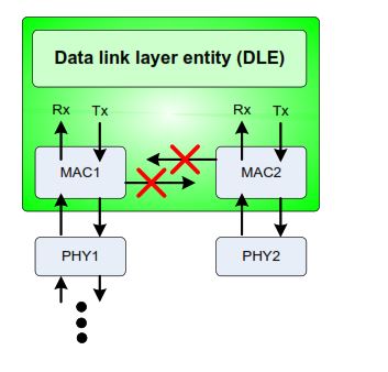
In line mode:
- Forwarding between MAC1 and MAC2 is blocked
- The device no longer forwards frames between its two ring ports
- The ring is converted into a logical line topology
As shown in the LNM forwarding diagram, the internal forwarding path inside the Data Link Layer Entity (DLE) is disabled. Frames are only transmitted and received through the remaining valid path.
This prevents loops and allows communication to continue using the alternate direction around the ring.
Recovery and Return to Ring Mode
When the fault is repaired:
- Devices detect link restoration
- A new RNM election is triggered if required
- RNMP and RNMS roles are reassigned
- Normal ring mode is restored automatically
No manual intervention or reset is required.
Key Characteristics of RNM and LNM Operation
- Fully automatic role assignment
- No predefined master device
- Deterministic and loop-free behavior
- Fast reaction based on physical link status
- Automatic adaptation to topology changes
- Clear separation between normal (RNM) and fault (LNM) operation
Network Control Messages in RRP
RRP devices continuously exchange Network Control Messages (NCMs) to maintain a consistent and up-to-date view of the network. These messages are essential for coordinating redundancy behavior across all devices in the ring.
Network control messages are used to:
- Announce link status, including link-up and link-down events
- Coordinate topology changes between ring and line modes
- Manage Ring Network Manager (RNM) roles, including election and re-election
By exchanging these messages, all RRP devices remain synchronized and can react immediately to topology changes. This distributed communication ensures deterministic behavior without relying on a central controller.
Failure Scenario: Cable or Device Loss
When a failure occurs in an RRP network—such as a cable break, port failure, or device power loss—the protocol reacts automatically.
The failure handling process works as follows:
- Link loss detection
The two devices adjacent to the fault detect the loss of Ethernet link at the physical layer. - Internal state change
These devices immediately change their internal forwarding state and stop normal ring operation. - Propagation of control messages
Network control messages are sent to inform all other devices about the topology change. - Removal of logical blocking
The blocking applied by the Ring Network Managers is removed. - Transition to line topology
The physical ring is converted into a logical line, allowing communication to continue using the remaining path.
This entire process is fully automatic, requires no manual intervention, and completes within a few milliseconds, ensuring high network availability.
RRP Recovery Time
Typical recovery times defined in IEC 62439-7:
- Up to 8 ms at 100 Mbps
- Up to 4 ms at 1 Gbps
These values depend on:
- Ring size
- Link speed
- Device processing time
This performance is sufficient for most industrial automation applications.
Return to Ring Mode
When the fault is repaired:
- Devices detect link restoration
- RNM election is repeated if needed
- The network returns to ring mode
- One direction is blocked again
No manual reset is required.
Path Selection and Hop Count
Each device maintains a path table containing:
- Destination device
- Hop count in both directions
- Forwarding port
The protocol always selects the shortest valid path while respecting the RNM block.
Address Management and Collision Handling
RRP uses UIDs to avoid problems caused by:
- Duplicate device addresses
- Configuration errors
If an address collision is detected:
- The condition is reported
- Communication remains deterministic
- Troubleshooting is simplified
Plug-and-Play Behavior
RRP supports dynamic network changes:
- Devices can be added or removed
- Topology is updated automatically
- No manual reconfiguration is required
This is especially useful in modular or expanding installations.
Performance Characteristics of RRP
Main performance properties:
- Deterministic forwarding
- No frame duplication
- Fast recovery
- Low bandwidth overhead
- Standard Ethernet compatibility
RRP intentionally avoids complex mechanisms to keep behavior predictable.
RRP vs HSR vs PRP
| Feature | RRP | HSR | PRP |
|---|---|---|---|
| Topology | Ring | Ring | Dual LAN |
| Recovery Time | ms | 0 | 0 |
| Frame Duplication | No | Yes | Yes |
| Hardware Cost | Low | Medium | High |
| Complexity | Low | High | Medium |
Typical Applications of RRP
RRP is commonly used in:
- Factory automation
- Process control systems
- Transportation networks
- Industrial machine networks
- Utility automation (non-process-bus)
It is best suited for systems where fast recovery is required but zero-time recovery is not mandatory.
Advantages of Ring-based Redundancy Protocol
- Standardized by IEC 62439-7
- Fast and predictable recovery
- Simple ring topology
- No special Ethernet switches required
- Lower cost compared to zero-time solutions
- Distributed redundancy intelligence
Limitations of RRP
- Recovery is not seamless
- Not suitable for time-critical protection traffic
- Limited mainly to ring topologies
- Less common in modern digital substations than PRP or HSR
Design Best Practices
When designing an RRP network:
- Use industrial-grade Ethernet hardware
- Limit ring size to reduce recovery time
- Document device addresses carefully
- Monitor diagnostics and alarms
- Avoid mixing redundancy protocols in the same ring
Final Conclusion
Ring-based Redundancy Protocol (RRP), defined in IEC 62439-7, is a practical and efficient solution for building reliable industrial Ethernet networks using a ring topology. By distributing redundancy intelligence across all devices, RRP provides fast recovery from single failures while keeping the network architecture simple and deterministic.
Although it does not offer zero recovery time like PRP or HSR, RRP remains a strong choice for many industrial automation applications where millisecond-level recovery is sufficient. Its standardized behavior, predictable performance, and ease of deployment make it a valuable redundancy option in modern industrial communication systems.