In industrial control and SCADA environments, the choice of communication protocol determines system reliability, latency, and security.
Two protocols dominate legacy and modern SCADA communication — Modbus and DNP3.
Although both serve similar functions (data exchange between a control center and field devices), they differ significantly in architecture, layer structure, and functional philosophy.
Modbus prioritizes simplicity and universality, while DNP3 emphasizes data integrity, event-driven efficiency, and resilience across large-scale, noisy networks.
Table of Contents
Protocol Origins and Design Philosophy
| Protocol | Developer | Year | Primary Domain |
|---|---|---|---|
| Modbus | Modicon (Schneider Electric) | 1979 | PLC-to-PLC / field automation |
| DNP3 | Harris Controls (now GE) | Early 1990s | SCADA, power utilities, critical infrastructure |
Modbus was designed for simple, cyclic polling in industrial control — one master continuously queries multiple slaves for register values.
DNP3, derived from the IEC 60870-5 family, was designed for asynchronous communication between control centers, RTUs, and IEDs — with deterministic, timestamped, and event-driven data handling.
Modbus vs DNP3: Layer Architecture
Modbus (Simplified Stack)
The Modbus protocol operates over both serial and Ethernet networks, and its architecture aligns loosely with the OSI (Open Systems Interconnection) model.
The diagram below illustrates how Modbus RTU and Modbus TCP map to the OSI layers.

Modbus Application Layer
At the top of the Modbus stack is the Application Layer, which defines:
- Function codes (e.g., Read Coils, Write Registers, Diagnostics)
- Data structure (registers, coils, discrete inputs)
- Exception handling mechanisms
This layer is common to both Modbus RTU and Modbus TCP. It represents Layer 7 (Application) in the OSI model and contains all the protocol logic required for data exchange.
Modbus RTU over Serial
In Modbus RTU, data transmission occurs over serial interfaces like EIA-485 (RS-485) or EIA-232 (RS-232).
It follows a simple master–slave architecture, where one master polls multiple slaves sequentially.
Layer mapping:
| OSI Layer | Modbus RTU Equivalent |
|---|---|
| 1. Physical | RS-232 / RS-485 electrical interface |
| 2. Data Link | Serial framing (start/stop bits, CRC-16) |
| 7. Application | Modbus function codes and registers |
Key characteristics:
- No transport, network, or session layers — messages are delivered as single, contiguous frames.
- Each Modbus RTU frame starts with a device address, followed by function code, data field, and a CRC checksum.
- Timing between bytes and silent intervals (3.5 character times) are critical for frame synchronization.
How Modbus TCP Works Over Ethernet
Modbus TCP adapts the traditional Modbus Application Layer to Ethernet networks.
Instead of serial communication, it encapsulates Modbus messages in TCP/IP packets, providing improved performance, scalability, and network reach.
Layer mapping:
| OSI Layer | Modbus TCP Equivalent |
|---|---|
| 1. Physical | IEEE 802.3 Ethernet |
| 2. Data Link | Ethernet MAC |
| 3. Network | Internet Protocol (IP) |
| 4. Transport | Transmission Control Protocol (TCP) |
| 7. Application | Modbus TCP function codes |
Technical details:
- The Modbus TCP header (MBAP) replaces the RTU address and CRC fields.
- The MBAP header includes:
- Transaction Identifier (2 bytes)
- Protocol Identifier (2 bytes)
- Length (2 bytes)
- Unit Identifier (1 byte)
- TCP ensures ordered, error-free delivery, so Modbus TCP omits the CRC checksum used in RTU.
Modbus’ stack structure reflects its evolution:
- Modbus RTU: A lightweight serial protocol designed for deterministic, low-overhead communication.
- Modbus TCP: A modern adaptation for Ethernet, leveraging TCP/IP for scalability, routing, and integration with enterprise networks.
While both share the same Application Layer, their underlying transport mechanisms differ greatly.
Modbus TCP’s reliance on standard networking layers (TCP/IP, Ethernet) makes it easier to integrate with IT infrastructure, while Modbus RTU remains ideal for direct field-level communication between PLCs, sensors, and actuators.
DNP3 EPA Architecture Explained
The DNP3 protocol is built upon a streamlined, high-performance communication framework known as the Enhanced Performance Architecture (EPA).
Unlike Modbus, which operates with a single application layer, DNP3 implements three well-defined layers derived from the OSI 7-layer model.
This structure provides stronger reliability, data integrity, and flexibility for wide-area SCADA communication.
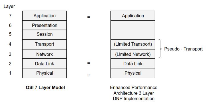
The diagram above shows how DNP3 condenses the OSI layers into a practical, efficient model suitable for industrial environments.
Physical Layer
The Physical Layer handles the actual transmission medium and electrical signaling between devices.
DNP3 supports multiple media types:
- Serial (EIA-232, EIA-485)
- Radio and Microwave Links
- Ethernet and TCP/IP Networks
This layer defines voltage levels, baud rates, timing, and synchronization, ensuring the reliable exchange of raw bits between outstations and masters.
Data Link Layer
The Data Link Layer is responsible for framing, addressing, and error checking.
It ensures that frames are correctly formed and verified before being passed upward.
Key characteristics:
- Each frame contains Start bytes, Length, Control, Destination, Source, and CRC fields.
- Cyclic Redundancy Check (CRC) is computed every 16 bytes, providing high integrity over noisy channels.
- Supports Acknowledgment (ACK), Negative Acknowledgment (NAK), and Retry mechanisms.
- Handles Primary (Master) and Secondary (Outstation) addressing.
The Data Link Layer in DNP3 provides end-to-end frame validation, ensuring that no corrupted data is ever passed to higher layers — a major improvement over Modbus.
Transport Layer (Pseudo-Transport)
Between the Data Link and Application layers, DNP3 includes a “Pseudo-Transport Layer.”
While not a full OSI transport implementation, it handles:
- Message segmentation and reassembly — splitting long messages into 249-byte frames.
- Sequence numbering for message fragments.
- Flow control to prevent buffer overflow or reordering.
This layer ensures that large application messages can be transmitted reliably, even over low-bandwidth or intermittent links such as radio networks.
Application Layer
The Application Layer is where the DNP3 protocol logic and intelligence reside.
It manages:
- Function codes (e.g., READ, WRITE, SELECT, OPERATE, DIRECT-OPERATE)
- Object groups and variations defining data types such as binary inputs, analogs, and counters
- Timestamped events (Sequence of Events – SOE)
- Unsolicited responses and report-by-exception messages
- Application confirmation and request sequencing
DNP3’s Application Layer is robust and extensible, enabling peer-to-peer communication and multi-master configurations — essential for distributed automation networks.
Communication Modes : Modbus vs DNP3
The communication mode defines how data is exchanged between the master (or control center) and field devices in a SCADA network.
While both Modbus and DNP3 support master–slave concepts, their communication philosophies differ significantly in terms of timing, responsiveness, and efficiency.
Modbus Communication Modes
Modbus operates strictly on a poll–response model.
The master initiates every transaction, and the slave devices respond only when queried.
Characteristics:
- Unidirectional control: Only the master can initiate communication.
- Cyclic polling: The master polls each device in sequence, regardless of whether data has changed.
- Timing: Communication speed depends on the number of devices and polling frequency.
- Determinism: Predictable communication cycles but inefficient for large or event-driven systems.
Modes of operation:
- Modbus RTU: Serial-based (RS-232/RS-485); uses timing gaps for frame separation.
- Modbus ASCII: Text-based, human-readable version; slower but easier to debug.
- Modbus TCP: Ethernet-based; encapsulates Modbus frames in TCP segments for faster, routable communication.
While simple and robust, Modbus’s constant polling can consume bandwidth unnecessarily and delay critical event reporting.
DNP3 Communication Modes
DNP3 supports multiple, more flexible communication modes designed for reliability and bandwidth efficiency.
Unlike Modbus, DNP3 allows event-driven communication in addition to traditional polling.
Modes of operation:
- Polled Mode:
The master requests specific data periodically — similar to Modbus but more efficient, as DNP3 supports class-based polling (Class 0, 1, 2, 3) to prioritize important data. - Unsolicited Mode:
The outstation (RTU/IED) initiates communication when significant events occur — known as Report-by-Exception (RBE).
This reduces network load and ensures critical changes are transmitted immediately. - Quiescent Mode:
Communication remains idle until triggered by an event or request, conserving bandwidth in low-activity networks. - Multimaster Mode:
DNP3 supports multiple masters communicating with the same outstation — allowing both primary and backup control centers to operate simultaneously.
Modbus vs DNP3: Data Organization
The way a protocol structures and represents process data directly impacts how efficiently it communicates and how easily it can be integrated into SCADA systems.
While Modbus uses a simple register-based memory model, DNP3 adopts a more descriptive and event-oriented object model designed for timestamping, classification, and quality tracking.
Modbus Data Model
Modbus organizes all process variables into addressable 16-bit registers.
Each register type serves a specific purpose, and data access is controlled through function codes defined at the Application Layer.
| Register Type | Address Range | Access Type | Typical Use |
|---|---|---|---|
| Coils | 0xxxx | Read/Write | Digital outputs (ON/OFF) |
| Discrete Inputs | 1xxxx | Read-only | Digital inputs or status signals |
| Input Registers | 3xxxx | Read-only | Analog inputs (sensor readings) |
| Holding Registers | 4xxxx | Read/Write | Analog outputs or configuration parameters |
Key Characteristics:
- Each register holds a 16-bit (2-byte) value.
- No metadata such as timestamp, data quality, or event status is included.
- The master must continuously poll to detect changes.
- Data semantics (engineering units, scaling, etc.) are typically handled in the SCADA software, not within the protocol.
This simplicity makes Modbus easy to implement but limits its ability to handle large-scale, time-sensitive, or asynchronous data efficiently.
DNP3 Data Model
In contrast, DNP3 structures data into Object Groups and Variations, where each group represents a data type and each variation defines its format and attributes.
This approach provides context, precision, and event-driven reporting capabilities.
| Object Group | Typical Data Type | Example Use |
|---|---|---|
| Group 1 | Binary Input | Switch or breaker status |
| Group 10 | Binary Output | Control relay output commands |
| Group 20 | Counter | Energy or pulse accumulators |
| Group 30 | Analog Input | Process variable measurements |
| Group 40 | Analog Output | Setpoints or control values |
| Group 50 | Time and Date | Time synchronization |
| Group 60 | Class Data (0/1/2/3) | Event prioritization |
| Group 120 | Authentication | DNP3 Secure Authentication (SA) data |
Key Characteristics:
- Each data point includes timestamp, quality flags, and event class.
- Outstations can buffer events and transmit only when data changes (Report-by-Exception).
- Supports multiple variations for the same object type (e.g., 16-bit, 32-bit, floating-point).
- Enables Select-Before-Operate (SBO) control sequences for secure and deterministic actuation.
This structured, event-oriented model allows DNP3 to maintain data integrity, historical accuracy, and bandwidth efficiency, even across unreliable communication links.
Modbus uses a flat and static memory map, requiring the master to continuously query each data point.
DNP3, however, employs a dynamic, context-rich object model that supports event-driven updates, timestamps, and quality flags — ideal for distributed and time-sensitive SCADA environments.
In essence:
- Modbus = Simple, register-based polling.
- DNP3 = Intelligent, event-driven data exchange.
Modbus vs DNP3: Security and Authentication
Modbus
Modbus TCP, while more modern than its serial predecessor, still inherits the same fundamental security weaknesses as traditional Modbus RTU.
The protocol was never designed with cybersecurity in mind — it assumes a trusted network environment and lacks mechanisms for user authentication, message integrity, or encryption.
Key security characteristics:
- No built-in authentication or encryption:
Any device on the same network can send Modbus requests and potentially manipulate registers or coils. - Susceptible to replay, spoofing, and injection attacks:
Because Modbus TCP uses plain-text communication over port 502 /TCP, attackers can capture and replay valid packets without detection. - No session or role management:
Each request is stateless and unauthenticated; devices cannot verify the identity or privilege level of the sender.
Typical mitigations:
- Deploy VPN tunnels or secure gateways to encapsulate traffic.
- Use network segmentation and firewalls to isolate control networks (often via port 502 filtering).
- Apply Modbus firewalls or DPI (Deep Packet Inspection) devices to validate requests.
- In critical systems, use Modbus Secure extensions (Modbus over TLS), which add certificate-based encryption and authentication, though adoption remains limited.
DNP3 (IEEE 1815-2012 and 1815-2020)
Unlike Modbus, DNP3 integrates security directly into its protocol standard.
The IEEE 1815-2012 specification introduced Secure Authentication (DNP3-SA), providing robust cryptographic protection against message forgery, replay, and unauthorized control operations.
Secure Authentication (IEEE 1815-2012 / SAv5):
- Challenge–response mechanism:
Each critical operation is verified through a cryptographic exchange using HMAC-SHA-256 or AES-GMAC. - Session and update keys:
Managed via symmetric key exchange, ensuring perfect forward secrecy and periodic key rotation. - Optional Authority Key:
Enables centralized key distribution or “trusted authority” management for large systems.
Enhanced Security (IEEE 1815-2020 / SAv6):
- Full encryption:
Adds AES-256-GCM authenticated encryption for both confidentiality and integrity. - Authorization Management Protocol (AMP):
Provides centralized role-based access control and device authorization. - Simplified enrollment and key rotation:
Uses the Low-Entropy Shared Secret (LESS) process for initial secure device enrollment and automated key updates.
Implementation and Diagnostic Tools
| Tool | Supported Protocols | Use |
|---|---|---|
| Wireshark | Modbus TCP, DNP3 TCP/UDP | Packet capture and protocol decoding |
| Kepware / ClearSCADA | Both | Simulation and driver integration |
| DNP3 Test Set (Triangle MicroWorks) | DNP3 | Conformance testing, security validation |
| Modbus Poll/Slave | Modbus RTU/TCP | Basic communication testing |
DNP3’s object-based model and event buffers make troubleshooting more involved but also provide more diagnostic data (e.g., sequence numbers, timestamps, quality flags).
When to Choose Modbus vs DNP3
| Application Area | Recommended Protocol | Reason |
|---|---|---|
| Factory PLC Networks | Modbus RTU/TCP | Simplicity, cost-effective |
| Substation Automation | DNP3 | Reliability, time tagging, security |
| Water/Wastewater SCADA | DNP3 | Long-distance comms, low bandwidth |
| Building Management Systems | Modbus | Wide device support |
| Power Distribution Control | DNP3 | SOE, unsolicited events, SA compliance |
Protocol Interoperability
Modern systems often bridge DNP3 and Modbus using protocol gateways.
For example:
- A Modbus RTU sensor connects to a DNP3 master through a gateway that converts Modbus register reads into DNP3 object updates.
- SCADA software like Kepware, Ignition, or OpenMUC can act as middleware supporting both protocols concurrently.
Conversion challenges:
- Modbus lacks timestamps → gateways must append system time.
- Register addressing must be mapped to DNP3 object variations.
- Data quality bits (flags) are usually synthesized.
Conclusion
Technically, both DNP3 and Modbus serve SCADA systems well — but their architectural differences define their suitability:
- Modbus excels in simple, local control where low cost and ease of use are priorities.
- DNP3 dominates in mission-critical, geographically dispersed networks where reliability, timestamping, and security are essential.
In short:
- Modbus = simplicity + ubiquity.
- DNP3 = robustness + intelligence + security.
For future-ready systems — especially those requiring compliance with modern cybersecurity standards — DNP3 (IEEE 1815) remains the protocol of choice.
Thanks Mr.Zakaria for this article, I appreciate your effort to explain the difference between Modbus and dnp3.