
Every ASDU (Application Service Data Unit) in IEC 60870-5-104 contains a Type ID — a single byte that defines what kind of data the message carries. It tells the receiving station whether the message contains a single-point indication, a measured value, a command, a counter, or a system message.
The Type ID is the first byte of every ASDU. If you misidentify it, you misinterpret the entire message.
IEC 104 shares the same Type IDs as IEC 60870-5-101 (defined in IEC 60870-5-101:2003, Section 7.2.1). This guide covers every Type ID used in IEC 104 — organized by category, with the ASDU name, numeric code, data format, and practical use case for each one.
Table of Contents
1. How Type IDs Work
The Type ID is the first field in the ASDU header:
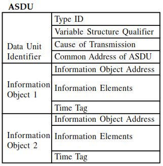
| Field | Size | Description |
|---|---|---|
| Type ID | 1 byte | Identifies the ASDU type (1–127) |
| Variable Structure Qualifier | 1 byte | Number of information objects + SQ bit |
| Cause of Transmission | 1 or 2 bytes | Why this ASDU was sent |
| Common Address of ASDU | 1 or 2 bytes | Station address |
| Information Object(s) | Variable | The actual data |
The Type ID determines:
- What kind of data the ASDU carries (single-point, double-point, measured value, command)
- What information elements are inside each information object (value, quality, timestamp)
- What direction the message travels (monitor = outstation → master, control = master → outstation)
2. Type ID Naming Convention
Every Type ID has a symbolic name following the pattern:
X_YY_ZZ_1| Part | Meaning | Values |
|---|---|---|
| X | Direction | M = Monitor (outstation → master), C = Control (master → outstation), P = Parameter, F = File |
| YY | Data type | SP = Single-Point, DP = Double-Point, ST = Step Position, BO = Bitstring, ME = Measured, IT = Integrated Totals, EP = Event Protection, SC = Single Command, DC = Double Command, SE = Set-point, IC = Interrogation, CI = Counter Interrogation, CS = Clock Sync |
| ZZ | Qualifier | NA = No time tag, TA = Time tag (3 bytes, CP24Time2a), TB = Time tag CP56Time2a, NC = Short float, ND = Normalized without quality |
| 1 | Always 1 | Indicates companion standard 101/104 |
Example: M_ME_TF_1 = Monitor direction, Measured value, short floating point with Time tag CP56Time2a.
3. Process Information in Monitor Direction (Type 1–40)
These ASDUs carry data from the outstation (RTU/IED) to the controlling station (SCADA master).
Single-Point and Double-Point Information
| Type ID | Name | Description | Time Tag |
|---|---|---|---|
| 1 | M_SP_NA_1 | Single-point information | None |
| 2 | M_SP_TA_1 | Single-point information | CP24Time2a (3 bytes) |
| 3 | M_DP_NA_1 | Double-point information | None |
| 4 | M_DP_TA_1 | Double-point information | CP24Time2a |
| 30 | M_SP_TB_1 | Single-point information | CP56Time2a (7 bytes) |
| 31 | M_DP_TB_1 | Double-point information | CP56Time2a |
Single-point = ON/OFF (1 bit). Used for: circuit breaker status, alarm state, digital input.
Double-point = four states: OFF (01), ON (10), Indeterminate (00), Indeterminate (11). Used for: circuit breaker position where intermediate and faulty states must be detected.
Step Position Information
| Type ID | Name | Description | Time Tag |
|---|---|---|---|
| 5 | M_ST_NA_1 | Step position information | None |
| 6 | M_ST_TA_1 | Step position information | CP24Time2a |
| 32 | M_ST_TB_1 | Step position information | CP56Time2a |
Used for: transformer tap changer position (-64 to +63).
Bitstring of 32 Bits
| Type ID | Name | Description | Time Tag |
|---|---|---|---|
| 7 | M_BO_NA_1 | Bitstring of 32 bits | None |
| 8 | M_BO_TA_1 | Bitstring of 32 bits | CP24Time2a |
| 33 | M_BO_TB_1 | Bitstring of 32 bits | CP56Time2a |
Used for: packed status bits, generic binary data where no other type applies.
Measured Values — Normalized
| Type ID | Name | Description | Time Tag |
|---|---|---|---|
| 9 | M_ME_NA_1 | Measured value, normalized | None |
| 10 | M_ME_TA_1 | Measured value, normalized | CP24Time2a |
| 21 | M_ME_ND_1 | Measured value, normalized without quality | None |
| 34 | M_ME_TD_1 | Measured value, normalized | CP56Time2a |
Normalized values are 16-bit signed integers representing a fraction of a full-scale range (-1.0 to +1.0, encoded as -32768 to +32767). Used for: percentage values, positions.
Measured Values — Scaled
| Type ID | Name | Description | Time Tag |
|---|---|---|---|
| 11 | M_ME_NB_1 | Measured value, scaled | None |
| 12 | M_ME_TB_1 | Measured value, scaled | CP24Time2a |
| 35 | M_ME_TE_1 | Measured value, scaled | CP56Time2a |
Scaled values are 16-bit signed integers with a scaling factor defined by the project. Used for: temperature, pressure, level — when integer representation is sufficient.
Measured Values — Short Floating Point
| Type ID | Name | Description | Time Tag |
|---|---|---|---|
| 13 | M_ME_NC_1 | Measured value, short floating point | None |
| 14 | M_ME_TC_1 | Measured value, short floating point | CP24Time2a |
| 36 | M_ME_TF_1 | Measured value, short floating point | CP56Time2a |
IEEE 754 single-precision float (4 bytes). Used for: voltage, current, power, frequency, energy — the most common measured value type in modern IEC 104 systems.
Integrated Totals (Counters)
| Type ID | Name | Description | Time Tag |
|---|---|---|---|
| 15 | M_IT_NA_1 | Integrated totals | None |
| 16 | M_IT_TA_1 | Integrated totals | CP24Time2a |
| 37 | M_IT_TB_1 | Integrated totals | CP56Time2a |
Used for: energy counters (kWh, kVarh), pulse counters.
Protection Equipment Events
| Type ID | Name | Description | Time Tag |
|---|---|---|---|
| 17 | M_EP_TA_1 | Event of protection equipment | CP24Time2a |
| 18 | M_EP_TB_1 | Packed start events of protection equipment | CP24Time2a |
| 19 | M_EP_TC_1 | Packed output circuit info of protection equipment | CP24Time2a |
| 38 | M_EP_TD_1 | Event of protection equipment | CP56Time2a |
| 39 | M_EP_TE_1 | Packed start events of protection equipment | CP56Time2a |
| 40 | M_EP_TF_1 | Packed output circuit info of protection equipment | CP56Time2a |
Used for: protection relay trip events, fault start detection, output circuit status.
Other Monitor Types
| Type ID | Name | Description |
|---|---|---|
| 20 | M_PS_NA_1 | Packed single-point information with status change detection |
4. Process Information in Control Direction (Type 45–69)
These ASDUs carry commands from the controlling station (SCADA master) to the outstation (RTU/IED).
Commands Without Time Tag
| Type ID | Name | Description |
|---|---|---|
| 45 | C_SC_NA_1 | Single command (ON/OFF) |
| 46 | C_DC_NA_1 | Double command (ON/OFF with intermediate states) |
| 47 | C_RC_NA_1 | Regulating step command (HIGHER/LOWER) |
| 48 | C_SE_NA_1 | Set-point command, normalized value |
| 49 | C_SE_NB_1 | Set-point command, scaled value |
| 50 | C_SE_NC_1 | Set-point command, short floating point |
| 51 | C_BO_NA_1 | Bitstring of 32 bits command |
Commands With CP56Time2a Time Tag
| Type ID | Name | Description |
|---|---|---|
| 58 | C_SC_TA_1 | Single command with time tag |
| 59 | C_DC_TA_1 | Double command with time tag |
| 60 | C_RC_TA_1 | Regulating step command with time tag |
| 61 | C_SE_TA_1 | Set-point command, normalized with time tag |
| 62 | C_SE_TB_1 | Set-point command, scaled with time tag |
| 63 | C_SE_TC_1 | Set-point command, short float with time tag |
| 64 | C_BO_TA_1 | Bitstring of 32 bits command with time tag |
Practical Use
- C_SC_NA_1 (45) — the most common command. Opens/closes a circuit breaker, starts/stops a pump.
- C_DC_NA_1 (46) — used when the target device uses double-point representation (breakers, disconnectors).
- C_RC_NA_1 (47) — raises/lowers a transformer tap changer one step.
- C_SE_NC_1 (50) — sends a floating-point set-point (e.g., voltage set-point to an AVR).
5. System Information in Monitor Direction (Type 70)
| Type ID | Name | Description |
|---|---|---|
| 70 | M_EI_NA_1 | End of initialization |
Sent by the outstation after it completes startup. The SCADA master uses this as a trigger to perform a general interrogation.
6. System Information in Control Direction (Type 100–107)
| Type ID | Name | Description |
|---|---|---|
| 100 | C_IC_NA_1 | Interrogation command (general interrogation or group) |
| 101 | C_CI_NA_1 | Counter interrogation command |
| 102 | C_RD_NA_1 | Read command (read a single information object) |
| 103 | C_CS_NA_1 | Clock synchronization command |
| 104 | C_TS_NA_1 | Test command |
| 105 | C_RP_NA_1 | Reset process command |
| 106 | C_CD_NA_1 | Delay acquisition command |
| 107 | C_TS_TA_1 | Test command with CP56Time2a |
Practical Use
- C_IC_NA_1 (100) — General Interrogation (GI). The master sends this after startup or reconnection. The outstation responds with all current data.
- C_CI_NA_1 (101) — Counter Interrogation. Requests current counter values.
- C_CS_NA_1 (103) — Clock Synchronization. Aligns the outstation’s clock with the master. Often replaced by NTP/PTP in modern systems.
7. Parameter in Control Direction (Type 110–113)
| Type ID | Name | Description |
|---|---|---|
| 110 | P_ME_NA_1 | Parameter of measured values, normalized |
| 111 | P_ME_NB_1 | Parameter of measured values, scaled |
| 112 | P_ME_NC_1 | Parameter of measured values, short floating point |
| 113 | P_AC_NA_1 | Parameter activation |
Used for: sending deadband and threshold settings to outstations. Less common in modern systems — most parameters are configured via engineering tools.
8. File Transfer (Type 120–127)
| Type ID | Name | Description |
|---|---|---|
| 120 | F_FR_NA_1 | File ready |
| 121 | F_SR_NA_1 | Section ready |
| 122 | F_SC_NA_1 | Call directory, select file, call file, call section |
| 123 | F_LS_NA_1 | Last section, last segment |
| 124 | F_AF_NA_1 | ACK file, ACK section |
| 125 | F_SG_NA_1 | Segment |
| 126 | F_DR_TA_1 | Directory |
Used for: retrieving disturbance records, fault logs, and event files from protection relays and RTUs.
9. The 10 Most Used Type IDs in IEC 104
In a typical power system SCADA installation, these 10 Type IDs account for over 95% of all traffic:
| Rank | Type ID | Name | Use |
|---|---|---|---|
| 1 | 36 | M_ME_TF_1 | Measured values with timestamp (voltage, current, power) |
| 2 | 30 | M_SP_TB_1 | Single-point indications with timestamp (breaker status, alarms) |
| 3 | 31 | M_DP_TB_1 | Double-point indications with timestamp (breaker position) |
| 4 | 100 | C_IC_NA_1 | General Interrogation |
| 5 | 13 | M_ME_NC_1 | Measured values without timestamp (cyclic polling) |
| 6 | 1 | M_SP_NA_1 | Single-point indications without timestamp (background scan) |
| 7 | 45 | C_SC_NA_1 | Single command (open/close breaker) |
| 8 | 37 | M_IT_TB_1 | Counter values with timestamp (energy metering) |
| 9 | 103 | C_CS_NA_1 | Clock synchronization |
| 10 | 70 | M_EI_NA_1 | End of initialization |
10. Type IDs with CP56Time2a Timestamps
In IEC 104, the CP56Time2a variant is strongly preferred over CP24Time2a for event reporting. CP56Time2a provides millisecond resolution with full date information (7 bytes).
| Without Timestamp | With CP24Time2a | With CP56Time2a | Data Type |
|---|---|---|---|
| 1 (M_SP_NA_1) | 2 (M_SP_TA_1) | 30 (M_SP_TB_1) | Single-point |
| 3 (M_DP_NA_1) | 4 (M_DP_TA_1) | 31 (M_DP_TB_1) | Double-point |
| 5 (M_ST_NA_1) | 6 (M_ST_TA_1) | 32 (M_ST_TB_1) | Step position |
| 7 (M_BO_NA_1) | 8 (M_BO_TA_1) | 33 (M_BO_TB_1) | Bitstring |
| 9 (M_ME_NA_1) | 10 (M_ME_TA_1) | 34 (M_ME_TD_1) | Measured, normalized |
| 11 (M_ME_NB_1) | 12 (M_ME_TB_1) | 35 (M_ME_TE_1) | Measured, scaled |
| 13 (M_ME_NC_1) | 14 (M_ME_TC_1) | 36 (M_ME_TF_1) | Measured, short float |
| 15 (M_IT_NA_1) | 16 (M_IT_TA_1) | 37 (M_IT_TB_1) | Integrated totals |
💡 Best practice: Use CP56Time2a types (30–40) for spontaneous event reporting. Use types without timestamp (1, 3, 9, 11, 13) for cyclic/background scan and general interrogation responses.
11. Quality Descriptors in Monitored Type IDs
Most monitored Type IDs include a quality descriptor byte. The quality bits are:
| Bit | Name | Meaning |
|---|---|---|
| 0 | OV | Overflow — measured value exceeded range |
| 4 | BL | Blocked — value is frozen/blocked by local operation |
| 5 | SB | Substituted — value has been replaced by an operator or system |
| 6 | NT | Not Topical — value is not current (e.g., communication lost) |
| 7 | IV | Invalid — value is not valid |
If bit 7 (IV) = 1, the value should not be trusted. SCADA systems typically show these points with a “bad quality” indicator.
Type 21 (M_ME_ND_1) is the exception — it has no quality descriptor. It is used for fast cyclic transmission where quality is assumed to be good.
12. Cause of Transmission and Type ID Relationships
The Cause of Transmission (COT) in the ASDU header tells the receiving station why the message was sent. Different Type IDs use different COT values:
| COT Value | Name | Typical Type IDs |
|---|---|---|
| 1 | Periodic/cyclic | 9, 11, 13 (measured values without timestamp) |
| 2 | Background scan | 1, 3, 9, 11, 13 (all without timestamp) |
| 3 | Spontaneous | 30, 31, 36 (events with CP56Time2a) |
| 5 | Requested (by GI) | 1, 3, 9, 11, 13, 30, 31, 36 (GI response) |
| 6 | Activation | 45, 46, 100 (commands, GI) |
| 7 | Activation confirmation | 45, 46, 100 (confirmation of command) |
| 10 | Activation termination | 45, 46, 100 (command execution complete) |
| 20 | Interrogated by station | 1, 3, 9, 11, 13 (GI group response) |
| 37 | Interrogated by group 1 | Group-specific interrogation response |
| 44 | Unknown Type ID | ASDU rejected by receiving station |
| 45 | Unknown COT | ASDU rejected — unknown cause |
| 46 | Unknown Common Address | ASDU rejected — wrong station address |
| 47 | Unknown IOA | ASDU rejected — unknown information object address |
13. Quick Lookup Table: All Type IDs
Monitor Direction (Outstation → Master)
| ID | Name | Description |
|---|---|---|
| 1 | M_SP_NA_1 | Single-point information |
| 2 | M_SP_TA_1 | Single-point with time tag CP24 |
| 3 | M_DP_NA_1 | Double-point information |
| 4 | M_DP_TA_1 | Double-point with time tag CP24 |
| 5 | M_ST_NA_1 | Step position information |
| 6 | M_ST_TA_1 | Step position with time tag CP24 |
| 7 | M_BO_NA_1 | Bitstring of 32 bits |
| 8 | M_BO_TA_1 | Bitstring with time tag CP24 |
| 9 | M_ME_NA_1 | Measured value, normalized |
| 10 | M_ME_TA_1 | Measured normalized with time tag CP24 |
| 11 | M_ME_NB_1 | Measured value, scaled |
| 12 | M_ME_TB_1 | Measured scaled with time tag CP24 |
| 13 | M_ME_NC_1 | Measured value, short float |
| 14 | M_ME_TC_1 | Measured short float with time tag CP24 |
| 15 | M_IT_NA_1 | Integrated totals |
| 16 | M_IT_TA_1 | Integrated totals with time tag CP24 |
| 17 | M_EP_TA_1 | Protection equipment event with time tag CP24 |
| 18 | M_EP_TB_1 | Packed protection start events with time tag CP24 |
| 19 | M_EP_TC_1 | Packed protection output circuit with time tag CP24 |
| 20 | M_PS_NA_1 | Packed single-point with status change detection |
| 21 | M_ME_ND_1 | Measured normalized without quality |
| 30 | M_SP_TB_1 | Single-point with time tag CP56 |
| 31 | M_DP_TB_1 | Double-point with time tag CP56 |
| 32 | M_ST_TB_1 | Step position with time tag CP56 |
| 33 | M_BO_TB_1 | Bitstring with time tag CP56 |
| 34 | M_ME_TD_1 | Measured normalized with time tag CP56 |
| 35 | M_ME_TE_1 | Measured scaled with time tag CP56 |
| 36 | M_ME_TF_1 | Measured short float with time tag CP56 |
| 37 | M_IT_TB_1 | Integrated totals with time tag CP56 |
| 38 | M_EP_TD_1 | Protection equipment event with time tag CP56 |
| 39 | M_EP_TE_1 | Packed protection start events with time tag CP56 |
| 40 | M_EP_TF_1 | Packed protection output circuit with time tag CP56 |
Control Direction (Master → Outstation)
| ID | Name | Description |
|---|---|---|
| 45 | C_SC_NA_1 | Single command |
| 46 | C_DC_NA_1 | Double command |
| 47 | C_RC_NA_1 | Regulating step command |
| 48 | C_SE_NA_1 | Set-point, normalized |
| 49 | C_SE_NB_1 | Set-point, scaled |
| 50 | C_SE_NC_1 | Set-point, short float |
| 51 | C_BO_NA_1 | Bitstring of 32 bits command |
| 58 | C_SC_TA_1 | Single command with time tag CP56 |
| 59 | C_DC_TA_1 | Double command with time tag CP56 |
| 60 | C_RC_TA_1 | Regulating step command with time tag CP56 |
| 61 | C_SE_TA_1 | Set-point normalized with time tag CP56 |
| 62 | C_SE_TB_1 | Set-point scaled with time tag CP56 |
| 63 | C_SE_TC_1 | Set-point short float with time tag CP56 |
| 64 | C_BO_TA_1 | Bitstring command with time tag CP56 |
System Information
| ID | Name | Description |
|---|---|---|
| 70 | M_EI_NA_1 | End of initialization |
| 100 | C_IC_NA_1 | Interrogation command |
| 101 | C_CI_NA_1 | Counter interrogation command |
| 102 | C_RD_NA_1 | Read command |
| 103 | C_CS_NA_1 | Clock synchronization command |
| 104 | C_TS_NA_1 | Test command |
| 105 | C_RP_NA_1 | Reset process command |
| 106 | C_CD_NA_1 | Delay acquisition command |
| 107 | C_TS_TA_1 | Test command with time tag CP56 |
Parameter
| ID | Name | Description |
|---|---|---|
| 110 | P_ME_NA_1 | Parameter, normalized |
| 111 | P_ME_NB_1 | Parameter, scaled |
| 112 | P_ME_NC_1 | Parameter, short float |
| 113 | P_AC_NA_1 | Parameter activation |
File Transfer
| ID | Name | Description |
|---|---|---|
| 120 | F_FR_NA_1 | File ready |
| 121 | F_SR_NA_1 | Section ready |
| 122 | F_SC_NA_1 | Call directory / select file |
| 123 | F_LS_NA_1 | Last section, last segment |
| 124 | F_AF_NA_1 | ACK file, ACK section |
| 125 | F_SG_NA_1 | Segment |
| 126 | F_DR_TA_1 | Directory |
Summary
The Type ID is the first byte of every IEC 104 ASDU. It defines what kind of data the message carries and how to decode the rest of the frame.
The key things to remember:
- Types 1–40 = monitor direction (outstation → master). Types 30–40 use CP56Time2a timestamps.
- Types 45–64 = control direction (master → outstation). Types 58–64 use CP56Time2a timestamps.
- Type 100 (C_IC_NA_1) = General Interrogation — the most important system command.
- Type 36 (M_ME_TF_1) = the most common measured value type in modern IEC 104 systems.
- Type 30 (M_SP_TB_1) and 31 (M_DP_TB_1) = the most common status indications with timestamps.
- Always check the quality descriptor — bit 7 (IV = Invalid) means the value should not be trusted.
- Use CP56Time2a types (30–40) for spontaneous events. Use types without timestamp for GI responses.
💡 Tip: Use the free IEC 104 Frame Decoder Tool to decode any IEC 104 frame byte by byte — including Type ID, Cause of Transmission, IOA, and data values.