
A complete reference for substation engineers comparing the IEC 61850 process bus and station bus — what each bus does, protocols used, hardware requirements, time synchronization needs, redundancy strategies, bandwidth, topology, and procurement considerations
Quick Comparison Table
| Aspect | Process Bus | Station Bus |
|---|---|---|
| Purpose | Real-time measurement + trip | SCADA, configuration, supervisory |
| Replaces | Analog CT/VT wiring + binary trips | Conventional RTU and SCADA wiring |
| Main protocols | Sampled Values (SV) + GOOSE | MMS + GOOSE |
| Standard | IEC 61850-9-2, IEC 61869-9 | IEC 61850-8-1 |
| Transport | Layer 2 Ethernet (no IP) | TCP/IP + Layer 2 GOOSE |
| Latency target | < 4 ms (protection) | 10–1000 ms (acceptable) |
| Time sync | PTP per IEC/IEEE 61850-9-3 (< 1 µs) | NTP/SNTP (~1 ms) acceptable |
| Bandwidth (per IED) | 5–20 Mbit/s | < 1 Mbit/s |
| Redundancy | PRP / HSR (0 ms recovery) | MRP / RSTP (10–500 ms) |
| Environmental | IEC 61850-3 / IEEE 1613 rated | Standard / industrial |
| Typical media | Single-mode / multi-mode fiber | Fiber or copper |
| Switch grade | Substation-hardened, hardware PTP | Industrial managed |
| Location | Switchyard + control room | Control room |
| Sync class required | T5 (1 µs) | T1–T3 (1 ms–10 ms) |
Introduction
The traditional substation used hundreds of kilometers of copper wiring to carry analog signals between CTs/VTs in the switchyard and protection relays in the control room. The IEC 61850 digital substation replaces that copper with two distinct Ethernet networks — each engineered for a specific purpose.
This article explains exactly what each bus does, how they differ, what hardware they need, and how they fit together in a complete digital substation architecture. Everything is verified against the IEC 61850 standard family.
Process Bus vs Station Bus — Quick Definition
In an IEC 61850 digital substation, the process bus is the high-speed network that carries real-time CT/VT measurements (Sampled Values) and trip commands (GOOSE) between Merging Units and protection IEDs. The station bus is the slower control-room network that carries SCADA traffic (MMS), engineering data, and supervisory commands between IEDs, the HMI, gateways, and engineering workstations. Process bus replaces analog wiring; station bus replaces conventional SCADA wiring.
Table of Contents
1. The Traditional Substation Architecture
Before IEC 61850, a typical substation had:
- Hundreds of copper cables running from the switchyard (CTs, VTs, breakers, disconnectors) to the relay panels
- One CT secondary winding per protection function — a transformer differential might need three relays, each with its own CT wiring
- Analog signal levels (1 A or 5 A for CTs, 100 V or 110 V for VTs)
- Hardwired binary signals for trips, interlocks, and breaker status (one wire per signal)
- Proprietary or RTU-based SCADA with Modbus, DNP3, or IEC 60870-5-101/104 over serial or copper
This worked, but had clear problems:
- Long cable runs caused analog signal distortion
- Burden management forced compromise on CT design
- Wiring errors were common and hard to find
- Adding a new IED meant running more copper
- Testing required isolating physical signals
- Cabinet space inside the control room ballooned
2. The Digital Substation Architecture
IEC 61850 introduces a layered network architecture:
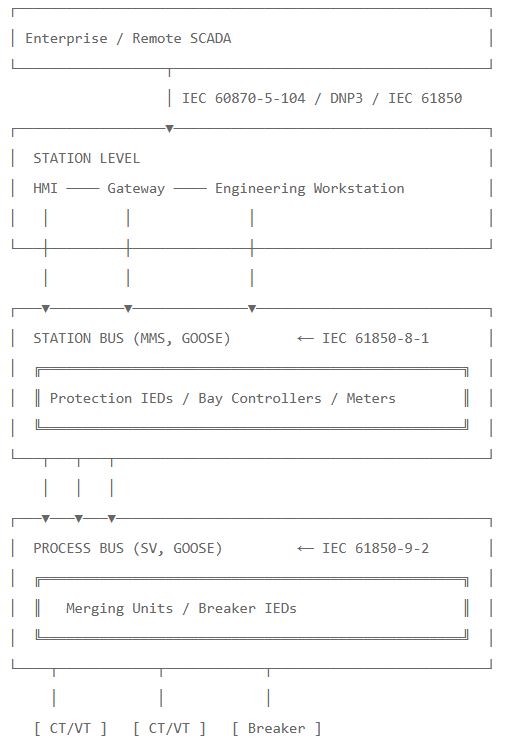
The architecture has three logical levels:
| Level | Purpose | Devices |
|---|---|---|
| Process level | Field measurement and switching | CTs, VTs, breakers, disconnectors, Merging Units |
| Bay level | Protection and control logic | Protection IEDs, bay controllers |
| Station level | Supervision, engineering, gateway | HMI, gateway, engineering tools |
Two buses connect these levels:
- Process bus — between process level and bay level
- Station bus — between bay level and station level
The same protection IED typically connects to both buses simultaneously — receiving SV from the process bus and exchanging MMS with the station bus.
3. What Is the Process Bus?
The process bus is the high-speed real-time network carrying CT/VT measurements and breaker control signals between the switchyard and the protection IEDs.
Process Bus Responsibilities
| Function | Protocol | Performance |
|---|---|---|
| CT/VT measurement transmission | Sampled Values (SV) | Continuous, < 2 ms processing delay |
| Trip and close commands | GOOSE | < 4 ms |
| Interlocks, position | GOOSE | < 4 ms |
| Time synchronization | PTP per IEC/IEEE 61850-9-3 | < 1 µs accuracy |
Process Bus Components
| Component | Role |
|---|---|
| Merging Unit (MU) | Digitizes CT/VT signals, publishes SV streams |
| Breaker IED / Switchgear Controller | Drives breaker, publishes position GOOSE |
| Protection IED | Subscribes to SV, runs algorithms, publishes trips via GOOSE |
| Process bus switch | Hardened, IEC 61850-3 / IEEE 1613 rated, hardware PTP |
| PTP grandmaster | GPS-locked time source for the whole substation |
| RedBox / QuadBox | For PRP/HSR redundancy gateways |
For the device producing SV streams, see: What Is a Merging Unit?
Process Bus Characteristics
- Layer 2 only — no TCP/IP routing
- Multicast-based — one publisher, many subscribers
- Deterministic timing — sub-millisecond latency, predictable jitter
- High bandwidth — 6–17 Mbit/s per SV stream
- Microsecond-level time synchronization required
- Zero recovery time redundancy (PRP/HSR) mandatory for protection
- Located in harsh environment — must withstand EMI, temperature, vibration
4. What Is the Station Bus?
The station bus is the supervisory network carrying SCADA data, configuration, reporting, and human-machine interaction between bay-level IEDs and station-level devices.
Station Bus Responsibilities
| Function | Protocol | Performance |
|---|---|---|
| Read measured values, status | MMS (IEC 61850-8-1) | 100–1000 ms acceptable |
| Control commands (open/close) | MMS or GOOSE | 100–500 ms |
| Event reports, alarms | MMS Buffered/Unbuffered Reports | 100–1000 ms |
| Configuration upload/download | MMS File Transfer | Seconds–minutes |
| Disturbance record retrieval | MMS File Transfer | Seconds |
| Cross-bay GOOSE (interlocking, sectionalizing) | GOOSE | < 100 ms |
| Time synchronization | SNTP / NTP | < 10 ms acceptable |
| Gateway to SCADA | IEC 60870-5-104, DNP3, OPC UA | 100–1000 ms |
Station Bus Components
| Component | Role |
|---|---|
| Protection IED | MMS server, GOOSE publisher/subscriber |
| Bay controller | Bay-level automation, SCADA gateway endpoint |
| HMI workstation | Operator console, alarm display |
| Station gateway | Translation to SCADA protocol (IEC 104, DNP3, OPC UA) |
| Engineering workstation | Configuration tools (CET, PCM600, etc.) |
| Station bus switch | Industrial managed switch, often IEC 61850-3 rated |
| NTP/SNTP server | Time source for non-critical sync |
Station Bus Characteristics
- TCP/IP for client/server (MMS uses TCP port 102)
- Layer 2 for GOOSE messages
- Lower bandwidth — < 1 Mbit/s per device typical
- Higher latency tolerated — 100 ms is normally fine
- Millisecond-level time sync sufficient
- Standard recovery times (MRP, RSTP) acceptable
- Located in control room — gentler environment than process bus
For the protocol that runs SCADA data over the station bus, see: IEC 61850 MMS Complete Guide
5. Side-by-Side Comparison
A deeper comparison across 15 dimensions:
| Dimension | Process Bus | Station Bus |
|---|---|---|
| Primary role | Real-time measurement + trip | Supervision + engineering |
| Replaces | Analog CT/VT wiring + binary control | RTU and SCADA wiring |
| Defined by | IEC 61850-9-2 + IEC 61869-9 | IEC 61850-8-1 |
| Primary protocols | Sampled Values + GOOSE | MMS + GOOSE |
| OSI layer | Layer 2 only | Layer 2 (GOOSE) + Layer 7 (MMS over TCP/IP) |
| EtherType / Port | 0x88BA (SV), 0x88B8 (GOOSE) | TCP 102 (MMS), 0x88B8 (GOOSE) |
| Communication model | Publisher/subscriber multicast | Client/server (MMS) + publisher/subscriber (GOOSE) |
| Typical latency | 1–4 ms end-to-end | 10–500 ms |
| Sync requirement | < 1 µs (PTP Power Profile) | < 10 ms (NTP/SNTP) |
| Bandwidth per node | 5–20 Mbit/s | 0.1–1 Mbit/s |
| Total aggregate BW | 60–500 Mbit/s for medium substation | 5–50 Mbit/s |
| Redundancy | PRP / HSR (0 ms) | MRP / RSTP (10–500 ms) |
| Physical layer | 100Base-FX or 1000Base-LX (fiber preferred) | Fiber or copper, 100/1000Base-T |
| Environment | Switchyard + control room (IEC 61850-3 / IEEE 1613) | Control room (industrial-grade sufficient) |
| Engineering tool | System configurator (SCD-based) | Same, plus IED-specific tools |
6. Protocols on Each Bus
Each bus uses a different mix of IEC 61850 protocols:
Process Bus Protocol Stack
| Protocol | Layer | Purpose |
|---|---|---|
| Sampled Values (SV) | Layer 2 | CT/VT digital samples (continuous) |
| GOOSE | Layer 2 | Trips, position, interlocks |
| PTP (IEC/IEEE 61850-9-3) | Layer 2 | Time synchronization |
| PRP / HSR | Layer 2 | Redundancy (optional) |
Station Bus Protocol Stack
| Protocol | Layer | Purpose |
|---|---|---|
| MMS (IEC 61850-8-1) | Layer 5–7 over TCP/IP | Client/server, read/write data, reports, file transfer |
| GOOSE | Layer 2 | Cross-bay control, interlocking (optional on station bus) |
| NTP / SNTP | UDP/IP | Time sync (sufficient for station-level apps) |
| MRP | Layer 2 | Ring redundancy |
| RSTP | Layer 2 | Rapid spanning tree (legacy, not recommended for time-critical) |
| HTTP / HTTPS | TCP/IP | Web-based engineering tools, web HMI |
Notice that GOOSE appears on both buses. The difference is the purpose:
- GOOSE on process bus — fast trips, breaker commands, sub-millisecond timing
- GOOSE on station bus — slower cross-bay interlocking, sectionalizing, blocking schemes
Some substations even use a single physical bus that carries both, separated only by VLAN. This is the two-bus logical / one-bus physical design (see Section 12).
7. Time Synchronization Differences
Time synchronization is the most critical difference between the two buses.
Process Bus Sync Requirements
Per IEC 61850-5 Table 3 synchronization classes:
| Sync Class | Accuracy | Required For |
|---|---|---|
| T5 | ±1 µs | Sampled Values for protection |
| T4 | ±4 µs | Sampled Values for measurement |
Achieved with PTP per IEC/IEEE 61850-9-3 (the Power Profile), which provides:
- Grandmaster accuracy: ≤ 250 ns
- Transparent clock contribution: ≤ 50 ns per hop
- Boundary clock contribution: ≤ 200 ns per hop
- Network-wide accuracy: < 1 µs across 15 TCs or 3 BCs
For complete PTP details, see: PTP Power Profile Explained (IEC/IEEE 61850-9-3)
Station Bus Sync Requirements
| Sync Class | Accuracy | Required For |
|---|---|---|
| T1 | ±1 s | Time-stamping of slow events |
| T2 | ±100 ms | Time-stamping of operational events |
| T3 | ±25 ms | Time-stamping of fast events |
Typically achieved with NTP or SNTP over UDP/IP. Some substations run PTP on the station bus as well — but it’s not mandatory.
Practical Impact
A station bus switch can be a standard industrial managed switch. A process bus switch must support hardware PTP timestamping with sub-nanosecond accuracy — this is a fundamentally different (and more expensive) device.
8. Network Hardware Differences
The hardware requirements diverge sharply between the two buses.
Process Bus Switch Requirements
| Requirement | Specification |
|---|---|
| Environmental rating | IEC 61850-3 + IEEE 1613 mandatory |
| PTP support | IEEE 1588v2 transparent clock or boundary clock, hardware timestamping |
| Throughput | Gigabit minimum, line-rate forwarding |
| Latency | Cut-through preferred (< 5 µs per hop) |
| VLAN support | IEEE 802.1Q mandatory |
| Multicast | IGMP snooping or static multicast tables |
| Redundancy | PRP and/or HSR (IEC 62439-3) support |
| Power | Redundant DC inputs (substation battery) |
| Temperature | −40 °C to +85 °C operating |
For substation-rated switches, see: IEC 61850-3 Ethernet Switch Requirements
Station Bus Switch Requirements
| Requirement | Specification |
|---|---|
| Environmental rating | IEC 61850-3 recommended but often relaxed |
| PTP support | Optional (SNTP usually sufficient) |
| Throughput | 100/1000 Mbit/s acceptable |
| Latency | Standard store-and-forward fine |
| VLAN support | IEEE 802.1Q recommended |
| Redundancy | MRP, RSTP commonly used |
| Power | Single AC or DC acceptable |
| Temperature | 0 °C to +60 °C often sufficient |
A typical Siemens RUGGEDCOM RST2228 (process bus rated) costs significantly more than a Hirschmann RSP-25 (station bus rated) — and rightfully so. The process bus switch is a specialized device.
9. Bandwidth Differences
Process Bus Bandwidth Calculation
A medium substation with 10 bays at preferred IEC 61869-9 rates:
| Component | Per Stream | Total |
|---|---|---|
| Protection SV (F4800S2I4U4) | ~6 Mbit/s | 60 Mbit/s |
| Metering SV (F14400S6I4U4) | ~17 Mbit/s | ~170 Mbit/s if used |
| GOOSE (cyclic + event) | < 0.5 Mbit/s | < 5 Mbit/s |
| PTP overhead | < 0.1 Mbit/s | < 1 Mbit/s |
| Total (protection only) | ~70 Mbit/s | |
| Total (protection + metering) | ~250 Mbit/s |
With PRP, this doubles on each LAN. With HSR, the ring sees doubled traffic at each node.
Gigabit Ethernet is the practical minimum for any process bus beyond a small substation.
Station Bus Bandwidth Calculation
A medium substation with 20 IEDs + HMI:
| Component | Per Device | Total |
|---|---|---|
| MMS polling | ~0.1 Mbit/s | ~2 Mbit/s |
| Event reports | ~0.1 Mbit/s peak | < 1 Mbit/s avg |
| Disturbance records (occasional) | ~5 Mbit/s burst | < 1 Mbit/s avg |
| GOOSE (if used) | < 0.2 Mbit/s | < 4 Mbit/s |
| Engineering uploads | ~5 Mbit/s burst | < 1 Mbit/s avg |
| Total typical | < 10 Mbit/s |
100 Mbit/s is usually sufficient for the station bus. Gigabit is used for headroom and future-proofing, not necessity.
10. Redundancy Strategies
The two buses use different redundancy approaches because their recovery time requirements differ dramatically.
Process Bus Redundancy
| Protocol | Recovery Time | Standard | Best For |
|---|---|---|---|
| PRP | 0 ms (truly zero) | IEC 62439-3 | Parallel networks, doubly-attached IEDs |
| HSR | 0 ms (truly zero) | IEC 62439-3 | Ring topology with HSR-aware devices |
Process bus protection cannot tolerate any disruption during a fault. A 10 ms outage during a transmission line fault could mean missing critical samples and protection misoperation. Hence zero recovery time is mandatory — PRP or HSR are the only acceptable choices.
Station Bus Redundancy
| Protocol | Recovery Time | Standard | Best For |
|---|---|---|---|
| MRP | 10–500 ms (configurable) | IEC 62439-2 | Ring topology, standard managed switches |
| RSTP | 50–2000 ms | IEEE 802.1w | Legacy networks, simple deployments |
| PRP | 0 ms | IEC 62439-3 | If using same hardware as process bus |
For SCADA, slow event reporting, and engineering tasks, MRP’s 10–500 ms recovery is fine. Operators tolerate brief HMI disconnections; SCADA polls eventually re-establish. No protection function depends on station bus delivery.
Common Mistake
Engineers sometimes specify PRP on the station bus “for consistency”. This is unnecessary cost — MRP delivers adequate availability for station-bus traffic at a fraction of the price. Conversely, never use MRP or RSTP on the process bus — protection will misoperate during recovery transitions.
11. Common Topologies
Process Bus Topologies
| Topology | Use Case |
|---|---|
| PRP dual-star | Most common for protection. Each MU and IED has two ports, one on LAN A and one on LAN B. |
| HSR ring | Compact bay rings. All devices form a ring; double-attached at the ring level. |
| Mixed HSR + PRP | HSR rings interconnected via PRP at the substation level (RedBox/QuadBox gateways). |
| Star (non-redundant) | Only for non-protection applications (metering, monitoring). |
Station Bus Topologies
| Topology | Use Case |
|---|---|
| MRP ring | Standard managed switches form a ring; one master, others as clients. |
| RSTP mesh | Legacy networks with multiple switches in mesh. Recovery time too slow for critical apps. |
| Star with redundant uplinks | Each IED to its bay switch; bay switches uplink to two station-level switches. |
| Dual star (PRP) | Some high-availability substations use PRP on the station bus too. |
12. Two-Bus vs Three-Bus Designs
The IEC 61850 standard doesn’t mandate two physical buses. The architecture is logical. Implementations vary:
Option 1: Two Physical Buses (Most Common)
[ Process Bus ]   ─ MUs, breaker IEDs, protection IEDs
[ Station Bus ]   ─ Protection IEDs, HMI, gateway, engineering
Each IED has two Ethernet interfaces — one to the process bus, one to the station bus. Clean separation, easy troubleshooting, independent bandwidth allocation.
Option 2: One Physical Bus with VLAN Separation
[ Single Physical Bus ]
   ├── VLAN 100 (Process Bus)
   ├── VLAN 200 (Station Bus)
   ├── VLAN 300 (PTP)
   └── VLAN 400 (Engineering)
Smaller substations may save cost by using one physical network with VLAN-based segmentation. This works if:
- Total bandwidth budget supports it (Gigabit minimum)
- Switches enforce VLAN isolation properly
- Priority tagging ensures process bus traffic is never blocked by station bus traffic
Option 3: Three Logical Buses
Larger or specialized substations may add a third bus — a separate “engineering bus” or “DMZ bus” — for:
- Cybersecurity (separating internal engineering from production)
- Cross-vendor data exchange
- External SCADA gateway
[ Process Bus ]   ─ Protection real-time traffic
[ Station Bus ]   ─ Internal supervision
[ Engineering Bus ] ─ Configuration tools, IT/OT DMZ
Which One to Choose?
| Substation Size | Recommended |
|---|---|
| Small (≤ 5 bays, no critical protection) | Single bus with VLANs |
| Medium (5–15 bays, standard protection) | Two physical buses |
| Large (≥ 15 bays, complex protection) | Two buses + dedicated engineering segment |
| Critical infrastructure (transmission HV) | Three logical buses, separate physical networks |
13. Greenfield vs Brownfield Migration
Greenfield (New Substation)
A new substation can adopt the full digital architecture immediately:
| Phase | Step |
|---|---|
| Design | Specify MUs, process bus switches, IEC 61869-9 SV profiles |
| Engineering | Build SCD with both station and process bus configurations |
| Commissioning | Test SV end-to-end with relay testers (CMC, FREJA) |
| Operation | Monitor PTP grandmaster health, SV stream availability |
Greenfield projects benefit from:
- Lower lifecycle cost (less copper, smaller cabinets)
- Faster commissioning (digital signals are testable in software)
- Better future-proofing (easy to add new IEDs)
Brownfield (Existing Substation Retrofit)
Retrofitting is more constrained:
| Approach | Description |
|---|---|
| Station bus only | Keep all CT/VT wiring; replace RTUs with IEC 61850-capable IEDs sharing data via MMS/GOOSE on station bus. Cheapest entry point. |
| Hybrid (mixed) | Add MUs for some bays (typically new transformers or feeders); keep analog wiring on existing bays. |
| Full digitalization | Replace all conventional CTs/VTs with electronic LPITs or add SAMUs. Most expensive but achieves full process bus benefits. |
The most common retrofit path is station bus first, process bus later — capture the easy wins immediately (engineering, SCADA modernization) without ripping out functional analog wiring.
14. Security Considerations per Bus
The two buses have different attack surfaces and security strategies.
Process Bus Security
| Concern | Mitigation |
|---|---|
| Unauthorized SV injection | Physical isolation, VLAN segmentation, port-based MAC restrictions |
| Frame manipulation | IEC 62351-6 (authentication only, no encryption) |
| Synchronization attack | Authenticated PTP per IEC 62351-9, GPS antenna physical protection |
| Denial of service | Rate limiting on switches, multicast filtering |
Process bus is typically air-gapped from corporate networks — no IP routing in or out. This drastically reduces attack surface.
Station Bus Security
| Concern | Mitigation |
|---|---|
| MMS unauthorized access | Client certificate authentication, role-based access |
| SCADA gateway compromise | Firewall, DMZ, deep packet inspection |
| Engineering workstation compromise | Endpoint protection, USB control, jump server |
| Network reconnaissance | VLAN segmentation, IDS/IPS, port lockdown |
| Cyber-physical attack on IEDs | IEC 62351-3 (TLS for MMS), patching, configuration backups |
Station bus is often the entry point for attackers because it interfaces with the IT side. Defense-in-depth is essential.
For threat modeling and IEC 62351 application, see: IEC 61850 Security Threats and IEC 62351 Protection
15. Procurement Considerations
When writing tender specifications, the buses require different procurement approaches.
Process Bus Procurement Checklist
- MUs certified to IEC 61869-9:2016 with specified variant codes (F4800S2I4U4 minimum)
- PTP per IEC/IEEE 61850-9-3 support mandatory
- Process bus switches: IEC 61850-3 + IEEE 1613, hardware PTP, cut-through, line-rate Gigabit
- PRP and/or HSR support (IEC 62439-3 Annex A/B)
- PTP grandmaster with GPS antenna, ≤ 250 ns accuracy
- Holdover specification for PTP master (typically ≥ 1 hour with OCXO)
- Maximum processing delay declared by every MU (typically ≤ 2 ms for protection)
- Third-party type test reports for all SV publishers and subscribers
Station Bus Procurement Checklist
- IEDs supporting IEC 61850-8-1 MMS with declared conformance class
- MMS file transfer support for SCL upload/download and disturbance records
- Station bus switches: managed Ethernet, VLAN, MRP support
- NTP/SNTP server for station-level time sync
- SCADA gateway: IEC 60870-5-104, DNP3, OPC UA bidirectional translation
- IED capacity: number of simultaneous MMS clients, buffered report capacity
- Engineering tool licenses for SCL editing and import
Joint Considerations
- Single SCD file describing both buses
- System configurator tool capable of multi-vendor integration
- Conformance testing at FAT and SAT for both buses
- Cybersecurity assessment per IEC 62443 / IEC 62351
16. Field Troubleshooting Patterns
🔴 Process Bus Specific
Pattern P1: SV stream gaps
- Cause: Network congestion, switch buffer overflow, subscriber CPU overload
- Action: Wireshark capture, verify switch port counters, reduce subscribed streams
Pattern P2: SmpSynch = 0
- Cause: PTP grandmaster unreachable, profile mismatch
- Action: Verify grandmaster clockClass = 6, check PTP profile is IEC/IEEE 61850-9-3, validate PRP/HSR path
Pattern P3: Differential protection misoperates
- Cause: SmpSynch mismatch between line ends, time jump during PTP re-lock
- Action: Verify both ends report SmpSynch = 2 (global), implement blocking logic during sync transitions
🔴 Station Bus Specific
Pattern S1: HMI shows stale data
- Cause: MMS report buffer overflow, lost TCP connection, MMS server overloaded
- Action: Check IED report log, restart MMS association, reduce polling rate
Pattern S2: GOOSE cross-bay interlock fails
- Cause: VLAN mismatch, GOOSE not crossing switch with VLAN filtering, GoCBRef not configured
- Action: Wireshark capture filtered on
eth.type == 0x88b8, verify VLAN ID and priority
Pattern S3: Engineering tool can’t read IED
- Cause: MMS client max-sessions exceeded, firewall blocking TCP 102, IP address conflict
- Action: Disconnect other clients, check firewall logs, ping IED IP
🔴 Cross-Bus
Pattern X1: Same IED works on station bus but not process bus
- Cause: Different VLAN configurations on two NICs, process bus PTP not configured
- Action: Verify each NIC has correct VLAN/MAC/PTP settings independently
Pattern X2: GOOSE works between IEDs but not from gateway
- Cause: Gateway connected to station bus only, GOOSE confined to process bus VLAN
- Action: Add GOOSE bridging at VLAN boundary or configure dual-attachment for the gateway
Summary
The process bus and station bus are the two parallel networks that together make up a digital IEC 61850 substation. They look similar (both Ethernet) but serve fundamentally different roles with very different engineering requirements.
Key Takeaways
- Process bus carries Sampled Values and GOOSE at sub-millisecond latency, replaces analog CT/VT wiring
- Station bus carries MMS and GOOSE at SCADA timescales, replaces conventional RTU wiring
- Time sync: Process bus needs PTP per IEC/IEEE 61850-9-3 (< 1 µs); station bus needs only NTP/SNTP (~10 ms)
- Redundancy: Process bus requires PRP or HSR (0 ms recovery); station bus can use MRP (10–500 ms)
- Bandwidth: Process bus aggregate is 60–500 Mbit/s; station bus aggregate is < 10 Mbit/s
- Hardware: Process bus switches need hardware PTP and IEC 61850-3 rating; station bus switches can be standard industrial
- Environment: Process bus equipment lives in or near the switchyard; station bus is control-room based
- Architecture options: Two physical buses (standard), one physical with VLANs (small substations), three logical buses (critical infrastructure)
- For procurement, never use station-bus hardware for process bus — protection will misoperate during redundancy events
- Always specify both buses independently in the tender — they’re not interchangeable