
A complete reference for substation engineers covering Sampled Values — IEC 61850-9-2 specification, frame structure, ASDU/APDU, SmpCnt and SmpSynch, ASN.1 BER encoding, multicast addressing, IEC 62351-6 security, PRP/HSR transport, and field troubleshooting
Quick Reference
| Item | Value |
|---|---|
| Standard | IEC 61850-9-2:2011 (Edition 2.0) + IEC 61869-9:2016 profile |
| Transport | Raw Ethernet (Layer 2), no TCP/IP |
| EtherType | 0x88BA |
| Multicast MAC range | 01-0C-CD-04-00-00 to 01-0C-CD-04-01-FF |
| APPID range | 0x4000–0x7FFF (default 0x4000 = “no config”) |
| Default VLAN priority | 4 (per IEEE 802.1Q) |
| Encoding | ASN.1 Basic Encoding Rules (BER) |
| Max APDU length | 1493 octets |
| Publisher | Merging Unit |
| Subscriber | Protection IED, meter, fault recorder |
| Service models | Multicast SV (MSVCB) + Unicast SV (USVCB) |
| Time sync | PTP per IEC/IEEE 61850-9-3 (preferred) or 1PPS |
| Security | IEC 62351-6 (optional, 28-bit reserved security field) |
Introduction
Sampled Values are one of three core protocols of IEC 61850, alongside GOOSE and MMS. While MMS carries SCADA-level configuration and reporting over TCP/IP, and GOOSE carries fast binary events at Layer 2, SV carries continuous high-rate analog measurements over Layer 2 Ethernet.
If GOOSE replaces binary control wiring, Sampled Values replace CT/VT analog wiring.
This article is the complete reference, verified against the IEC 61850-9-2:2011 Edition 2.0 specification and the IEC 61869-9:2016 profile. It covers frame structure, encoding rules, addressing, synchronization, security, network engineering, and field troubleshooting.
Table of Contents
1. What Are Sampled Values?
Sampled Values (SV) are real-time digital current and voltage measurements published as Ethernet multicast frames per IEC 61850-9-2. A Merging Unit digitizes CT and VT signals at a fixed sample rate, time-stamps each sample, and continuously streams them on the process bus where any protection IED, meter, or fault recorder can subscribe. SV replaces analog CT/VT wiring with deterministic, time-aligned digital communication.
2. Why Sampled Values Exist
Before SV, substations relied on analog CT/VT wiring — often hundreds of meters of copper from the switchyard to the control room. This created multiple problems:
- Analog signal distortion over distance
- Electromagnetic interference on long cable runs
- High copper cost
- CT burden and saturation issues
- Safety risks during maintenance (open CT secondary)
- One CT/VT could feed only one relay; sharing required wiring duplication
With Sampled Values:
- A Merging Unit (MU) digitizes the signal at the switchyard
- Samples travel through fiber/Ethernet, not copper
- Multiple IEDs subscribe to the same SV stream
- No analog distortion or noise once digitized
- Time-aligned samples enable cross-bay protection (differential, distance)
This architecture — called the IEC 61850 Process Bus — is the backbone of digital substations.
For the device producing SV streams, see: What Is a Merging Unit?
3. SV vs GOOSE vs MMS — When to Use Each
The three protocols in IEC 61850 serve different purposes:
| Aspect | MMS | GOOSE | Sampled Values |
|---|---|---|---|
| Purpose | Client/server, SCADA, config | Fast binary events | Continuous analog samples |
| Transport | TCP/IP (Layer 5–7) | Layer 2 Ethernet | Layer 2 Ethernet |
| EtherType | (uses TCP port 102) | 0x88B8 | 0x88BA |
| Data type | Any (structured) | Binary status, integers | Analog samples + quality |
| Behavior | Request/response | Event-driven multicast | Continuous streaming |
| Speed | 10–1000 ms | 1–4 ms | µs-level timing |
| Bandwidth | Low | Low | High (5–18 Mbit/s per stream) |
| Typical source | IED | Protection relay | Merging Unit |
| Replaces what? | Configuration UI | Binary copper wiring | CT/VT analog wiring |
| Standard | IEC 61850-8-1 | IEC 61850-8-1 | IEC 61850-9-2 |
In practice, all three operate simultaneously in a digital substation:
- MMS for HMI, engineering, supervisory monitoring
- GOOSE for trips, interlocks, position changes
- SV for the continuous measurement stream that feeds protection algorithms
4. The IEC 61850 Stack — Where SV Fits
IEC 61850-9-2 defines an SV-specific communication profile using direct Layer 2 Ethernet. There is no IP, no TCP, no UDP in the SV path.
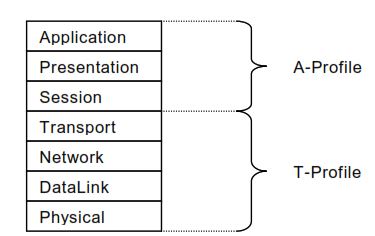
SV A-Profile (Application + Presentation Layers)
| Layer | Specification |
|---|---|
| Application | IEC 61850-9-2 SV service |
| Presentation | ASN.1 BER (ISO/IEC 8824-1, 8825-1) |
| Session | (Not used for SV) |
SV T-Profile (Transport to Physical Layers)
| Layer | Specification |
|---|---|
| Transport, Network | (Not used — SV bypasses these) |
| Link Redundancy | IEC 62439-3 (PRP / HSR) — optional |
| Data Link | IEEE 802.1Q (Priority tagging/VLAN) + ISO/IEC 8802-3 (CSMA/CD) |
| Physical | 100Base-FX fiber optic (recommended) |
This minimal stack is why SV is fast: no protocol overhead between the application and the wire.
Client/Server Access to SV Control Blocks
While the SV stream itself bypasses IP, management of the SV Control Block (enable/disable, configuration read/write) uses standard IEC 61850-8-1 MMS over TCP/IP. This is the only place where TCP/IP is involved with SV — and even that is optional (the SVCB may be pre-configured).
5. The SV Communication Model (Publisher/Subscriber)
SV uses a publisher/subscriber model — not client/server. The publisher (typically a Merging Unit) continuously broadcasts SV frames to a multicast MAC address. Any device interested subscribes by receiving multicast traffic from that address.
Key Characteristics
- Continuous streaming — SV never stops sending, even with no fault
- One-to-many — a single stream feeds protection, backup, fault recorder, meter simultaneously
- No acknowledgment — publisher doesn’t know who’s listening
- Stateless — each frame is self-contained
- Deterministic — frames arrive at fixed intervals
Typical Subscribers
- Primary protection relay
- Backup protection relay
- Bay controller
- Disturbance/fault recorder
- Power quality meter
- Wide-area monitoring system (PMU)
- Test equipment / simulators
All receive the same data simultaneously without any per-subscriber configuration on the publisher side.
6. Multicast (MSVCB) vs Unicast (USVCB) SV
IEC 61850-9-2 defines two SV service models:
| Aspect | Multicast SV (MSVCB) | Unicast SV (USVCB) |
|---|---|---|
| Destination | Multicast MAC address | Specific subscriber’s MAC |
| Subscribers | One-to-many | One-to-one |
| Reservation | Open to all | Exclusive (Resv flag) |
| Common use | Process bus measurement distribution | Specific point-to-point flow |
| Field deployment | Standard | Rare |
Multicast (MSVCB) is the dominant model in real-world substations. The unicast model exists for special-purpose applications where a dedicated point-to-point flow is required (typically inside an MU for diagnostic data).
This article focuses on multicast SV from this point forward.
7. The Sampled Value Control Block
The Multicast Sampled Value Control Block (MSVCB) is the IEC 61850 object that controls how a Merging Unit publishes SV streams. It plays the same role for SV that the GOOSE Control Block (GoCB) plays for GOOSE — but for continuous high-speed streams instead of event-driven messages.
Key MSVCB Attributes (IEC 61850-9-2 Table 9)
| Attribute | Type | Purpose |
|---|---|---|
MsvCBNam | Identifier | MMS name of this control block |
SvEna | Boolean | Enable/disable transmission — TRUE = streaming, FALSE = stopped |
MsvID | VisibleString | System-wide unique stream identifier |
DatSet | Reference | Data set defining which samples to publish |
ConfRev | Integer | Configuration revision counter — increments on any change |
SmpRate | Integer | Sample rate (interpreted per SmpMod) |
OptFlds | BitString | Optional fields included in each frame |
SmpMod | Enum | 0 = samples per nominal period, 1 = samples per second, 2 = seconds per sample |
DstAddress | Structure | Destination MAC, VLAN, APPID — see Section 8 |
noASDU | Integer | Number of ASDUs concatenated per APDU |
OptFlds Recommendations (per IEC 61869-9)
| Optional Field | IEC 61869-9 Setting |
|---|---|
refresh-time | FALSE |
sample-synchronised | TRUE (ignored, kept for backward compatibility) |
sample-rate | FALSE |
data-set | FALSE |
security | FALSE (TRUE only when IEC 62351-6 security is active) |
Excluding optional fields keeps frames compact and reduces bandwidth.
8. The SV Frame Structure
Each SV message is a standard IEEE 802.3 Ethernet frame with IEEE 802.1Q VLAN tagging. The complete structure from IEC 61850-9-2 Annex A:
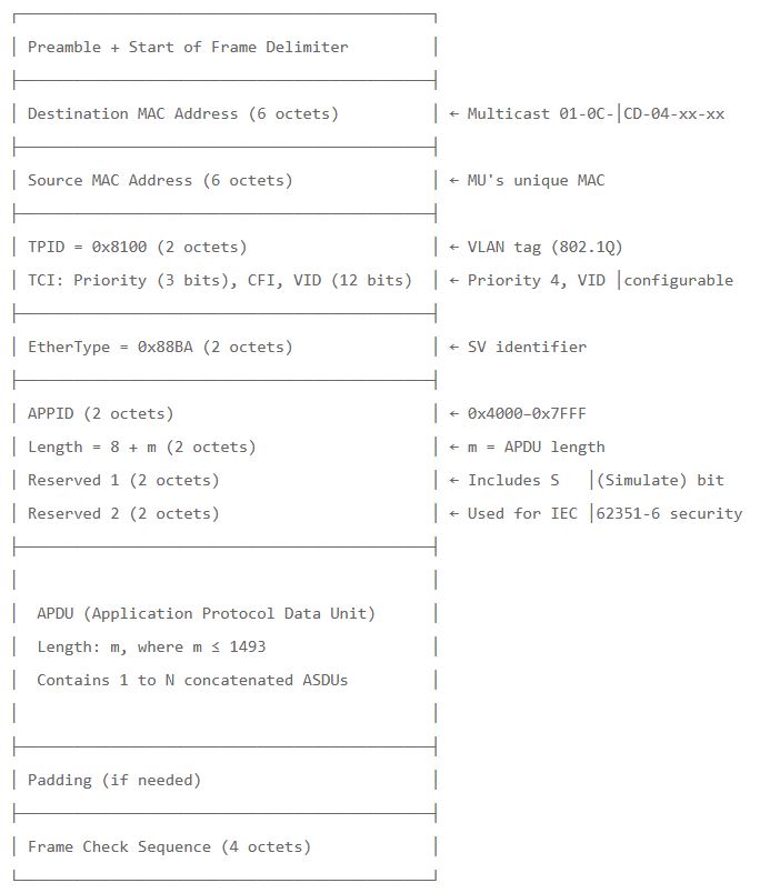
Maximum Frame Sizes
| Configuration | Max Frame Size |
|---|---|
| No link redundancy | 1521 octets |
| HSR redundancy | 1527 octets (+6 for HSR tag) |
| PRP redundancy | 1527 octets (+6 for PRP trailer) |
9. Multicast MAC Address Allocation
IEC 61850-9-2 Annex B specifies the recommended multicast address structure:
01 - 0C - CD - 04 - xx - xx
└──┴──┴──┴── IEEE-assigned for IEC 61850
            └── 04 = Multicast Sampled Values
                  (01 = GOOSE, 02 = GSSE)
xx-xx = stream-specific, assigned during engineering| Service | Recommended Range |
|---|---|
| GOOSE | 01-0C-CD-01-00-00 to 01-0C-CD-01-01-FF |
| GSSE | 01-0C-CD-02-00-00 to 01-0C-CD-02-01-FF |
| Multicast SV | 01-0C-CD-04-00-00 to 01-0C-CD-04-01-FF |
This range gives 512 unique SV stream addresses per substation — more than sufficient for any practical deployment.
⚠️ Important: Each SV stream should have a unique multicast MAC address within the network. Identical destination MACs cause subscribers to misidentify streams. Most network configuration tools enforce uniqueness at engineering time.
10. APPID and VLAN Configuration
APPID (Application Identifier)
The APPID is a 16-bit identifier in the Ethertype PDU that allows fast filtering at the link layer:
- Reserved range for SV:
0x4000to0x7FFF - Default value:
0x4000(indicates “no configuration” — should be replaced during engineering) - Recommendation: Each SV stream gets a unique APPID for source-oriented filtering
VLAN Tag
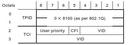
| Field | Value |
|---|---|
| TPID | 0x8100 (fixed per IEEE 802.1Q) |
| Priority | 4 (default) — higher than normal traffic, lower than GOOSE if separated |
| CFI | 0 (must be reset) |
| VID | 0 (default) — configure unique VID per VLAN segmentation |
Priority Strategy
Per IEEE 802.1Q recommendations:
- Priority 0 — Avoid (causes unpredictable delay)
- Priority 1 — Untagged frames default
- Priority 2–3 — Lower priority bus traffic
- Priority 4 — Sampled Values default
- Priority 5–7 — Time-critical (PTP, GOOSE trips)
VLAN Segmentation
Per IEC 61850-9-2 recommendations:
- SV and GOOSE should use different VIDs so they can be bandwidth-allocated independently
- Process bus VLAN should be separate from station bus VLAN
- This ensures aggregate SV traffic does not interfere with MMS or other Layer 3 traffic
11. ASDU vs APDU — The Concatenation Model
Inside the SV frame, the APDU is the “envelope” that contains one or more ASDUs.
ASDU (Application Service Data Unit)
One ASDU = one snapshot in time containing:
| Field | Description |
|---|---|
svID | Stream identifier |
datset | Data set reference (optional) |
smpCnt | Sample counter (16-bit) |
confRev | Configuration revision |
refrTm | Refresh time (optional) |
smpSynch | Synchronization status |
smpRate | Sample rate (optional) |
sample | The actual data values per the data set |
smpMod | Sample mode (optional) |
APDU (Application Protocol Data Unit)
An APDU contains:
| Field | Description |
|---|---|
savPdu | Application tag |
noASDU | Number of ASDUs in this APDU (1 to 65535) |
security | Optional security field (IEC 62351-6) |
asdu | Sequence of ASDUs (oldest first) |
Why Concatenate?
Concatenating multiple ASDUs into one APDU reduces frame overhead. For example, the preferred IEC 61869-9 protection variant F4800S2I4U4 sends 2 ASDUs per frame at 4800 sps, producing 2400 frames/second instead of 4800.
The trade-off is latency: a frame with 2 ASDUs is sent only when both ASDUs are ready, adding one sample interval of delay to the first ASDU.
For protection applications, noASDU = 1 or 2 is typical. For metering, noASDU = 6 or 8.
12. SmpCnt — The Sample Counter
The Sample Counter (SmpCnt) is a 16-bit unsigned integer (INT16U) that uniquely identifies each sample within the current second.
Behavior
- Increments with every new sample
- Resets to 0 at every synchronization pulse (top of second)
- Wraps back to 0 after reaching 65535 (only for very high sample rates ≥96 kHz)
Why It Matters
Subscribers use SmpCnt to:
- Detect missed samples (gaps in the counter)
- Align samples from multiple MUs (sample #1234 from MU-A = sample #1234 from MU-B if both synced)
- Time-stamp samples without needing the network refresh time
High Sample Rate Behavior (96 kHz)
At 96000 samples/second:
- Counter overflows back to 0 after sample 65535
- Continues counting up to 30463 (96000 − 65536 − 1)
- Represents the lower 16 bits of an internal 17-bit counter
- Real top of second is when SmpCnt transitions from 30463 to 0
13. SmpSynch — Synchronization Status Values
The SmpSynch attribute tells subscribers about the time synchronization source. From IEC 61850-9-2 Table 14:
| Value | Meaning | When Safe for Cross-Bay Functions |
|---|---|---|
| 0 | Not synchronized (free-running or holdover expired) | ❌ Local-only measurements |
| 1 | Synchronized to a local area clock (unspecified ID) | ⚠️ Only if all MUs share the same local clock |
| 2 | Synchronized to a global area clock (GPS, NTP, time-traceable) | ✅ Universal — all global-synced MUs aligned |
| 3, 4 | Reserved — do not use | — |
| 5–254 | Synchronized to specific local clock with this ID | ✅ Same ID = same clock = aligned |
| 255 | Reserved — do not use | — |
Practical Use Guidance
| Application | Required SmpSynch |
|---|---|
| Local overcurrent protection (single bay) | Any (even 0 works) |
| Voltage protection (single bay) | Any |
| Differential protection (line, transformer, bus) | ≥ 1 with matching clock source |
| Distance protection with remote endpoints | ≥ 1 with matching clock source |
| Synchrophasor (PMU) | = 2 (global clock required) |
| Wide-area monitoring | = 2 |
The Merging Unit publishes a current SmpSynch value in every ASDU. If sync is lost, the value drops to 0 and protection logic can take blocking action.
For PTP-based synchronization, see: PTP Power Profile Explained (IEC/IEEE 61850-9-3).
14. The Simulate (S) Flag — Testing in Live Systems
The Reserved 1 field includes a single bit S (Simulate) at bit 7 of octet 0. Per IEC 61850-9-2 Section 5.3.3.4.4:
“When this flag is set, the SampledValue telegram has been issued by a publisher located in a test device and not by the publisher as specified in the configuration file of the device.”
Why This Matters
In a live substation, you may need to inject test SV streams (e.g., from a CMC Omicron, Megger relay tester, or simulator) alongside the real MU streams. The S flag tells subscribers which is real and which is test.
Subscriber Behavior
When the S flag is set:
- Test mode subscriber: Accept and process the test SV stream
- Normal mode subscriber: Ignore the test frame — continue using the real MU stream
- The decision is made per-IED based on its configured operating mode
This mechanism allows engineers to test protection schemes against a known waveform without disconnecting the actual MU. Without the S flag, test injection would conflict with production data.
15. ASN.1 BER Encoding for SV Data Types
SV uses ASN.1 Basic Encoding Rules (BER) per ISO/IEC 8825-1 with a Type-Length-Value (TLV) format. From IEC 61850-9-2 Table 15:
Basic Data Type Encoding
| IEC 61850-7-2 Type | Encoding |
|---|---|
BOOLEAN | 8-bit (0 = FALSE, anything else = TRUE) |
INT8 | 8-bit big-endian signed |
INT16 | 16-bit big-endian signed |
INT32 | 32-bit big-endian signed (used for SAV.instMag.i) |
INT64 | 64-bit big-endian signed |
INT8U | 8-bit big-endian unsigned |
INT16U | 16-bit big-endian unsigned |
INT24U | 24-bit big-endian unsigned |
INT32U | 32-bit big-endian unsigned |
FLOAT32 | 32-bit IEEE 754 |
FLOAT64 | 64-bit IEEE 754 |
ENUMERATED | 32-bit big-endian |
CODED ENUM | 32-bit big-endian |
OCTET STRING | 20 bytes ASCII, null-terminated |
VISIBLE STRING | 35 bytes ASCII, null-terminated |
UNICODE STRING | 20 bytes ASCII, null-terminated |
TimeStamp | 64-bit timestamp per IEC 61850-8-1 |
EntryTime | 48-bit timestamp per IEC 61850-8-1 |
BITSTRING (per 8-1) | 32-bit big-endian |
Key Implication for Decoders
The 32-bit signed integer representation of instMag.i gives a dynamic range of ±2 147 483 647 counts. Combined with the IEC 61869-9 scaling factors (0.001 for amps in mA, 0.01 for volts in cV), this allows:
- Current: up to ±2 147 483 A peak (2.1 MA) — handles fault currents well beyond any practical CT range
- Voltage: up to ±21 474 836 V (21.4 MV) — covers any HV/EHV system
ASN.1 TLV Example
A complete ASDU has this structure (simplified):
30 [Length] svID    [0] [Length] [Value]
            datset  [1] [Length] [Value]   (optional)
            smpCnt  [2] [Length=2] [Value]
            confRev [3] [Length=4] [Value]
            refrTm  [4] [Length] [Value]   (optional)
            smpSynch[5] [Length=1] [Value]
            smpRate [6] [Length=2] [Value] (optional)
            sample  [7] [Length=N] [Value]
            smpMod  [8] [Length=2] [Value] (optional)
Each TLV triplet allows decoders to skip unknown fields and handle optional elements gracefully.
16. Sample Rates (IEC 61869-9 Preferred Values)
The original IEC 61850-9-2 standard did not mandate specific sample rates. IEC 61869-9:2016 filled this gap with preferred rates:
| Sample Rate | ASDUs/Frame | Frames/sec | Application |
|---|---|---|---|
| 4000 sps | 1 | 4000 | 9-2LE backward compat (50 Hz) |
| 4800 sps | 1 | 4800 | 9-2LE backward compat (60 Hz) |
| 4800 sps | 2 | 2400 | Preferred — protection/measurement |
| 5760 sps | 1 | 5760 | 60 Hz with 96 samples/cycle |
| 14400 sps | 6 | 2400 | Preferred — quality metering |
| 12800 sps (deprecated) | 8 | 1600 | 9-2LE legacy 50 Hz |
| 15360 sps (deprecated) | 8 | 1920 | 9-2LE legacy 60 Hz |
| 96000 sps | 1 | 96000 | High-bandwidth DC control |
The preferred protection rate (F4800S2I4U4) and preferred metering rate (F14400S6I4U4) both produce 2400 frames/second — a frequency-independent network rate that simplifies engineering.
For the variant code notation, see: What Is a Merging Unit?
17. PRP and HSR for SV Streams
Protection-grade SV networks require zero-recovery-time redundancy. IEC 61850-9-2 supports both PRP and HSR per IEC 62439-3.
PRP (Parallel Redundancy Protocol)
The MU has two Ethernet ports, one to LAN A and one to LAN B. Every SV frame is sent simultaneously on both LANs. The subscriber receives both and processes the first arrival, discarding the duplicate.
- Recovery time: zero (no detection or reconfiguration)
- Frame overhead: 6-byte PRP trailer (Sequence number + LAN ID + Suffix)
- Max frame size: 1527 octets (vs 1521 without redundancy)
HSR (High-availability Seamless Redundancy)
The MU is a node in a ring. Every SV frame is sent in both ring directions simultaneously. The receiver gets two copies; the second is discarded.
- Recovery time: zero (for any single break in the ring)
- Frame overhead: 6-byte HSR tag (Path + Size + Sequence number)
- Max frame size: 1527 octets
Bandwidth Doubling
Both PRP and HSR duplicate every SV frame on each network path. A 10-bay substation at F4800S2I4U4:
- Per LAN (PRP) or per ring direction (HSR): ~60 Mbit/s SV traffic
- Plus GOOSE, PTP, MMS
- Gigabit Ethernet strongly recommended for any non-trivial PRP/HSR deployment
For full PRP details, see: Parallel Redundancy Protocol (PRP) Complete Guide For HSR details, see: HSR (High-Availability Seamless Redundancy)
18. IEC 62351-6 Security for SV
IEC 61850-9-2 reserves a 28-bit security field (Reserved 2 + 4 bits of Reserved 1) for use by IEC/TS 62351-6, the security standard for IEC 61850.
What IEC 62351-6 Provides
| Feature | Status |
|---|---|
| Frame authentication | Optional |
| Source verification | Optional |
| Anti-replay protection | Optional |
| Frame encryption | NOT applied to SV/GOOSE (would break real-time performance) |
Why Not Encryption?
Encrypting SV would add latency that breaks protection-class real-time requirements (sub-millisecond). Instead, IEC 62351-6 uses HMAC-SHA256 for authentication only — the SV payload remains plaintext but is signed so subscribers can verify it came from a legitimate publisher.
Activating Security
When IEC 62351-6 security is enabled:
MSVCB.OptFlds.security= TRUE- The 28-bit security field carries authentication data
- Subscribers verify the signature; failed verification → discard frame
Adoption Status
IEC 62351-6 security is rarely deployed in production substations due to:
- Performance overhead (still measurable even without encryption)
- Key management complexity
- Limited vendor support
- Industry preference for network-level isolation (separate VLAN, separate physical network)
Most digital substations rely on physical isolation and network segmentation rather than cryptographic authentication.
19. Network Bandwidth Sizing
SV streams generate continuous high-rate traffic. Bandwidth planning is mandatory.
Per-Stream Bandwidth
| Variant Code | Frames/sec | Frame Size | Bandwidth |
|---|---|---|---|
| F4000S1I4U4 | 4000 | ~150 B | ~5 Mbit/s |
| F4800S1I4U4 | 4800 | ~150 B | ~6 Mbit/s |
| F4800S2I4U4 (preferred protection) | 2400 | ~300 B | ~6 Mbit/s |
| F14400S6I4U4 (preferred metering) | 2400 | ~900 B | ~17 Mbit/s |
| F96000S1I4U4 | 96000 | ~150 B | ~120 Mbit/s |
Aggregate Bandwidth Examples
| Substation Size | Streams | Total SV BW | Recommended Network |
|---|---|---|---|
| 4 bays, protection only | 4 | ~24 Mbit/s | 100 Mbit/s OK |
| 10 bays, protection only | 10 | ~60 Mbit/s | 100 Mbit/s tight, Gigabit recommended |
| 10 bays, protection + metering | 20 | ~230 Mbit/s | Gigabit required |
| 20 bays, full | 40 | ~460 Mbit/s | Gigabit required |
Maximum Quantities per Stream (IEC 61869-9)
To prevent network blocking from oversized frames on 100 Mbit/s networks:
| Application | Max I+U Quantities |
|---|---|
| General measuring/protection | 24 |
| Quality metering | 8 |
| DC control | 24 |
No limits apply for Gigabit and faster networks.
20. Network Engineering Requirements
A poorly engineered process bus causes delayed samples and relay misoperation. Required elements:
Mandatory
- VLAN tagging (IEEE 802.1Q) with VID and priority configured
- Multicast filtering at switch level (IGMP snooping or static multicast tables)
- Deterministic switching (cut-through preferred, store-and-forward acceptable for SV)
- Hardware MAC filtering capable of handling SV multicast load
- Time synchronization (PTP per IEC/IEEE 61850-9-3 or 1PPS)
Strongly Recommended
- PRP or HSR redundancy for protection-grade applications
- Gigabit Ethernet for any deployment beyond a few SV streams
- Dedicated process bus VLAN separate from station bus
- IEC 61850-3 / IEEE 1613 rated switches for substation environments
- Hardware PTP timestamping in switches (transparent clock)
Avoid
- RSTP on the process bus (recovery too slow)
- Mixing corporate/IT traffic on the process bus
- Routing SV between subnets (Layer 2 only)
- Consumer-grade Ethernet switches
- Default APPID (0x4000) in production
For network switches in substations, see: IEC 61850-3 Ethernet Switch Requirements
21. SV Performance and Latency
End-to-end SV latency from primary side to subscriber:
| Component | Typical Delay |
|---|---|
| Primary CT/VT response | < 1 µs |
| MU anti-aliasing filter | ~100–200 µs |
| MU ADC + processing | ~200–500 µs |
| MU total (processing delay) | ≤ 2 ms (IEC 61869-9 protection limit) |
| Switch (cut-through, per hop) | ~3–10 µs |
| Switch (store-and-forward, per hop) | 50–150 µs |
| Subscriber receive + decode | ~50–200 µs |
| Total end-to-end | typically 2–3 ms |
IEC 61869-9 Maximum Processing Delay (MU side only)
| Application | Limit |
|---|---|
| Quality metering | 10 ms |
| Protection and measurement | 2 ms |
| Time-critical low-bandwidth DC control | 100 µs |
| High-bandwidth DC control | 25 µs |
Why Phase Error ≠ Delay
A common misunderstanding: SV processing delay does NOT cause phase error. The encoded SmpCnt field timestamps the sample with the actual sampling instant. Subscribers use this timestamp to reconstruct phasors — not the time of frame arrival. Thus delay affects fault detection time but not measurement accuracy.
22. Procurement Specification Template
Required Standards
- IEC 61850-9-2:2011 compliance
- IEC 61869-9:2016 profile compliance
- IEC/IEEE 61850-9-3 for time synchronization
- IEC 61850-10 conformance testing
Required Capabilities
- EtherType 0x88BA SV publishing
- Multicast SV (MSVCB) mandatory
- Unicast SV (USVCB) optional
- IEEE 802.1Q VLAN tagging with configurable VID and priority
- PRP and/or HSR support per IEC 62439-3
- Simulate (S) flag handling per IEC 61850-9-2
Required Variant Codes (IEC 61869-9)
F4800S2I4U4— preferred protection/measurementF14400S6I4U4— preferred quality metering- Legacy variants (F4000S1I4U4 / F4800S1I4U4) if 9-2LE compatibility needed
Subscriber Requirements
- Multicast frame reception and filtering on configured MAC + APPID + VLAN
- SmpSynch value handling (0, 1, 2, 5–254)
- SmpCnt continuity monitoring (gap detection)
- ConfRev mismatch handling
- Simulate (S) flag mode handling (test vs production)
- Maximum number of simultaneous SV subscriptions
Documentation
- PICS, PIXIT, MICS (IEC 61850-10 compliant)
- ICD file with full SCL declaration
- Performance benchmarks (max subscribed streams, max processing delay)
- Third-party conformance test report
23. Field Troubleshooting: Common Failure Patterns
When working on site, these are the patterns to check first.
🔴 Pattern 1: Subscriber receives no SV stream
Likely causes:
SvEna = FALSEin the MSVCB- Wrong multicast MAC address configured on subscriber
- IGMP snooping blocking the multicast on the switch
- VLAN mismatch between publisher and subscriber
Actions:
- Verify
SvEna = TRUEusing system configurator - Wireshark capture on the subscriber side, filter
eth.type == 0x88ba - Check switch multicast forwarding tables
- Verify VLAN tags match end-to-end
🔴 Pattern 2: SmpSynch stuck at 0
Likely causes:
- PTP grandmaster unreachable
- PTP profile mismatch (default IEEE 1588 vs IEC/IEEE 61850-9-3)
- 1PPS signal lost or jittery beyond ±2 µs
- MU still in startup, hasn’t acquired sync yet
- Sync source lost > MU holdover time
Actions:
- Check PTP master diagnostics, clockClass = 6 (synced) or 7 (holdover)
- Verify PTP domain matches MU expectation (domain 93 if following IEC/IEEE 61850-9-3 recommendation)
- For 1PPS, measure signal quality at MU input
- Allow 30+ seconds after power-on for steady state
🔴 Pattern 3: ConfRev mismatch
Likely causes:
- MU configuration changed after subscribers were commissioned
- Data set membership/order modified
- SCD regeneration without subscriber update
Actions:
- Compare publisher’s
ConfRevagainst each subscriber’s configured value - Re-engineer subscribers if MU dataset changed
- Verify data set member order matches subscriber expectation
🔴 Pattern 4: Subscriber reads wrong values
Likely causes:
- Scaling factor mismatch (subscriber doesn’t apply 0.001 for mA → A)
- Wrong CT/VT ratio on subscriber
- Data set member order differs from subscriber expectation
- Wrong TCTR/TVTR instance interpretation (subscriber reading B-phase as A-phase)
Actions:
- Verify scaling:
AmpSv.instMag.iis in milliamperes (multiply by 0.001 for amperes);VolSv.instMag.iis in centivolts (multiply by 0.01 for volts) - Check substation section of SCL for phase-to-instance binding
- Confirm data set order in publisher matches subscriber’s decoding
🔴 Pattern 5: SmpCnt gaps (missing samples)
Likely causes:
- Network congestion / dropped frames
- Subscriber CPU overload (can’t keep up with frame rate)
- Switch buffer overflow
- Hardware fault on MU output port
Actions:
- Wireshark capture, check for gaps in
smpCntsequence - Verify switch port statistics (drops, errors)
- Reduce subscriber load (subscribe to fewer streams or use lower rate)
- Inspect cable and SFP module quality
🔴 Pattern 6: Duplicate APPID conflict
Likely causes:
- Two MUs configured with the same APPID (e.g., both at default
0x4000) - Engineering tool didn’t enforce uniqueness
- Manual configuration error
Actions:
- Each SV stream needs a unique APPID in
0x4000–0x7FFF - Wireshark shows duplicate APPIDs immediately when capturing
- Re-run system configurator to enforce uniqueness
🔴 Pattern 7: Network bandwidth saturation
Likely causes:
- Too many SV streams on 100 Mbit/s network
- PRP/HSR doubling traffic without bandwidth headroom
- Switch CPU overload from multicast snooping
- Mixed VLAN traffic on same broadcast domain
Actions:
- Calculate total SV bandwidth (Section 18)
- Upgrade to Gigabit Ethernet if approaching 50% link utilization
- Implement IGMP snooping or static multicast filters
- Segment SV onto dedicated VLAN
🔴 Pattern 8: Test injection accidentally affects production
Likely causes:
- Test SV stream did NOT set the Simulate (S) bit
- Subscriber not configured to filter by S flag
- Same APPID as production stream
Actions:
- Verify test equipment sets S = 1
- Configure subscriber test mode to accept S = 1 streams
- Use different APPID for test streams when possible
🔴 Pattern 9: Differential protection misoperates after sync change
Likely causes:
- One end’s MU running in free-run mode (SmpSynch = 0)
- Two ends synced to different local clocks (both SmpSynch = 1, different sources)
- Time jump > sample interval during PTP re-lock causes SmpCnt discontinuity
Actions:
- Verify both ends report SmpSynch = 2 (global) or matching ID in 5–254 range
- Check PTP grandmaster coverage at both ends
- Implement blocking logic during sync state transitions
🔴 Pattern 10: Cannot decode SV in Wireshark
Likely causes:
- Wireshark version too old (< 2.0 may not have native SV decoder)
- VLAN tag stripping by capture interface
- SPAN port losing VLAN information
Actions:
- Update Wireshark to latest version
- Use proper SPAN configuration that preserves VLAN tags
- Filter
eth.type == 0x88bato isolate SV - Apply IEC 61850 dissector preferences for custom decode
For Wireshark-based GOOSE analysis (similar technique applies to SV), see: Decoding IEC 61850 GOOSE Messages with Wireshark
Summary
Sampled Values are the foundation of the IEC 61850 process bus. They replace analog CT/VT wiring with deterministic, time-aligned digital streams that any number of IEDs can simultaneously consume.
Key Takeaways
- SV operates on Layer 2 Ethernet with EtherType 0x88BA, multicast MAC
01-0C-CD-04-xx-xx, default VLAN priority 4 - The current authoritative profile is IEC 61869-9:2016 (replaces 9-2LE)
- Publisher/subscriber model — publishers (MUs) broadcast, any subscriber can consume
- MSVCB (multicast) is the standard model; USVCB (unicast) rarely used
- Each frame is ASN.1 BER encoded with TLV structure
- APDU can contain 1 to N ASDUs — concatenation reduces overhead but adds latency
- SmpCnt identifies each sample within the second; resets to 0 at sync pulse
- SmpSynch values: 0 (not synced), 1 (local clock), 2 (global clock), 5–254 (specific local IDs)
- Simulate (S) bit distinguishes test streams from production
- AmpSv scaled in milliamperes, VolSv in centivolts (per IEC 61869-9 Tables 904/906)
- Preferred protection rate: F4800S2I4U4 = 4800 sps × 2 ASDU = 2400 frames/sec
- Preferred metering rate: F14400S6I4U4 = 14400 sps × 6 ASDU = 2400 frames/sec
- PRP/HSR doubles bandwidth on each path — plan for Gigabit Ethernet on anything non-trivial
- IEC 62351-6 security is optional; most deployments use network-level isolation instead
- Maximum SV processing delay: 2 ms for protection per IEC 61869-9