The RS-485 communication standard is the backbone of many industrial and building automation systems. It allows robust and reliable data transfer across distances of up to 4,000 feet (1,200 meters) using cost-effective twisted pair cabling.
This guide provides practical RS-485 wiring recommendations for RS-485 controllers, helping installers and engineers avoid communication failures and ensure long-term system stability.
Table of Contents
Understanding RS-485 Operation
Two-Wire and Three-Wire Configurations
RS-485 networks use two main signal lines — A+ (positive) and B– (negative) — for differential data transmission. A third conductor (GND) acts as a reference ground.
A two-wire RS-485 setup operates in half-duplex mode, meaning data travels in one direction at a time. All connected devices can transmit or receive, but only one device can transmit at any given moment.
Device Identification
Each device has a Device ID and a Network ID, both configurable by the user. These IDs enable devices to communicate using protocols such as BACnet MS/TP, allowing auto-configuration and even hot swapping without disrupting the network.
Recommended Network Topology
Daisy Chain Configuration (Preferred)
For reliable communication, the daisy chain topology is the industry standard. Devices are connected sequentially — each device linked to the next with minimal wire branching.
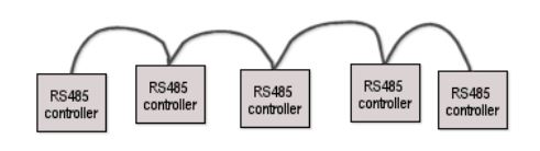
Avoid star topologies, as they introduce signal reflections and impedance mismatches that degrade data integrity.
Pro Tip: Keep the length of untwisted wire between devices as short as possible to prevent noise and interference.
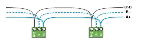
Correct Daisy Chain RS-485 Wiring Procedure
- Use a 3-pin terminal block (A+, B–, GND).
- Connect A+ from the upstream device to the local A+ terminal, and continue to the downstream A+.
- Repeat for B– and GND.
- If using multi-pair cable, dedicate one twisted pair for A+ and B–, and another for the ground wire.
- Terminate unused pairs with 100-ohm resistors to ground at both cable ends.
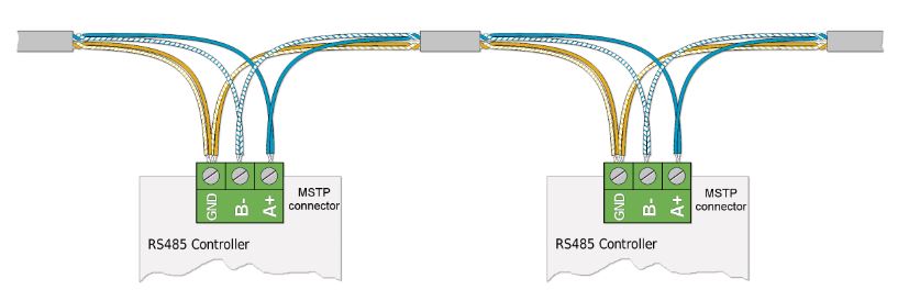
Keep wire insulation stripping short (~¼ inch), twist paired wires tightly, and avoid over-tightening terminal screws.
Grounding Best Practices
Importance of a Common Ground
RS-485 is a three-wire system — a shared ground reference is mandatory. Proper grounding minimizes voltage potential differences and prevents data corruption.
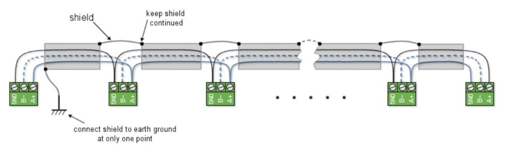
If using shielded twisted pair cable, connect the shield to earth ground at one end only to avoid ground loops. A loop can induce unwanted currents that interfere with communication.
Tip: When connecting devices from different manufacturers, always verify signal naming. “A+” may also appear as “+”, “B–” as “–”, and “GND” as “┴” or “r”.
Termination and Fail-Safe Biasing
Why Termination Matters
RS-485 networks behave like transmission lines — reflections can occur if the line isn’t terminated properly, leading to data corruption.
Install termination resistors at both ends of the network segment to absorb signal reflections.

Fail-Safe Biasing Explained
When no device is transmitting (the “idle” state), the RS-485 line can float and pick up electrical noise. Fail-safe biasing keeps the line in a defined logic state during idle periods, preventing false triggering.
Only end-of-line devices should have termination and fail-safe bias enabled. Intermediate nodes must have these circuits disabled.
Segment Length and Device Limits
- Maximum devices per segment: 32
- Maximum segment length: 4,000 ft (1,200 m)
- Minimum cable distance between devices: 1 ft (30 cm)
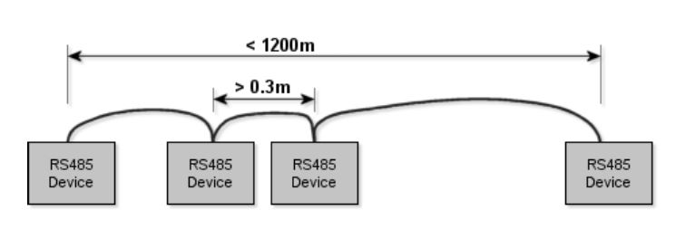
If you need more than 32 devices or longer distances, use router devices to interconnect multiple RS-485 segments.
Recommended RS-485 Cable Specifications
| Parameter | Specification |
|---|---|
| Cable Type | 2 twisted pairs |
| Conductor Gauge | ≤ AWG 24 stranded |
| Shield | Yes, braided (≥ 80% coverage) |
| Mutual Capacitance | < 20 pF/ft @ 1 kHz |
| Ground Capacitance | < 30 pF/ft @ 1 kHz |
| Characteristic Impedance | 100–120 Ω |
| Conductor DCR | ≤ 26 Ω/1000 ft |
| Shield DCR | ≤ 2.5 Ω/1000 ft |
Use shielded twisted pair with a dedicated ground wire for best noise immunity.
Troubleshooting Common RS-485 Wiring Issues
| Problem | Likely Cause | Solution |
|---|---|---|
| Communication loss | Missing termination | Add 120Ω terminators at both ends |
| Data corruption | Star topology or excessive stubs | Rewire into daisy chain |
| Unstable communication | Ground loop | Ground shield at one point only |
| Random data frames | Idle line noise | Enable fail-safe biasing |
Conclusion
Proper RS-485 wiring and grounding are essential for reliable network communication. By following the guidelines for daisy chain topology, correct termination, and shield grounding, installers can achieve stable, interference-free communication across large industrial or automation systems.
For advanced setups, always consult the manufacturer’s specifications and use high-quality shielded twisted pair cables designed for RS-485 applications.