PROFIsafe is a functional safety communication protocol that runs on top of PROFIBUS or PROFINET. It allows safety-critical data — emergency stop signals, light curtain outputs, safety door interlocks — to travel on the same cable as standard control data, without requiring a separate safety bus.
In the IEC standards framework, PROFIsafe is defined as FSCP 3/1 (Functional Safety Communication Profile 3/1) in IEC 61784-3-3:2016. It applies to all CPF 3 communication profiles: CP 3/1 (PROFIBUS DP), CP 3/2 (PROFIBUS PA), CP 3/4, CP 3/5, and CP 3/6 (PROFINET IO).
The fundamental design principle: the underlying communication network is treated as a “black channel.” PROFIsafe makes no assumptions about the reliability of the cable, switches, repeaters, or protocol layers beneath it. It implements all safety measures in the application layer, entirely above the standard protocol. This means the same safety protocol works identically over PROFIBUS, PROFINET, fiber optic, copper, and even wireless networks — with no changes.
Table of Contents
Why PROFIsafe Exists: The Problem With Standard Fieldbuses
A standard PROFIBUS or PROFINET network is designed for reliable communication — but “reliable” in the automation sense is not the same as “safe” in the functional safety sense. Standard networks can:
- Lose messages without the receiver knowing
- Deliver messages out of sequence
- Insert spurious messages from faulty switches or repeaters
- Repeat old messages that were stored in network buffers
- Misroute messages to the wrong device
For standard I/O, any of these events causes a process disruption at worst. For safety I/O — a light curtain guarding a robot, an emergency stop protecting a person — any of these events could prevent a protective device from functioning when needed, potentially causing injury or death.
PROFIsafe adds a safety layer that detects every one of these failure modes and responds with a defined safe state before harm can occur.
The Black Channel Principle
The black channel is the cornerstone of PROFIsafe’s architecture. It means:
The entire standard communication infrastructure — cables, connectors, switches, ASICs, protocol stacks — is treated as an opaque, untrusted transport. PROFIsafe makes no assumptions about what happens inside it. It does not rely on the network’s own error detection (FCS, CRC at the frame level, retry mechanisms) for safety purposes.
Instead, PROFIsafe adds its own safety measures entirely in the F-Host and F-Device software. The standard network just carries the bytes. PROFIsafe checks whether those bytes are valid, authentic, and timely — independently of whatever the network itself may have done.
This approach has a major practical advantage: the black channel does not need to be safety-assessed. A standard PROFINET switch, a standard repeater, a standard PROFIBUS coupler — none of these need TÜV approval or safety certification just because PROFIsafe traffic passes through them. The safety proof is entirely in the F-Host and F-Device implementations.
The Four Safety Measures
IEC 61784-3-3 specifies exactly four safety measures that PROFIsafe uses to master all possible transmission errors. Each failure mode maps to one or more of these measures:
| Communication Error | MonitoringNumber | Watchdog + Receipt | Codename | CRC (Data Integrity) |
|---|---|---|---|---|
| Corruption | — | — | — | ✓ |
| Unintended repetition | — | ✓ | — | — |
| Incorrect sequence | ✓ | — | — | — |
| Loss | ✓ | ✓ | — | — |
| Unacceptable delay | — | ✓ | — | — |
| Insertion | ✓ | — | — | — |
| Masquerade | — | — | — | ✓ |
| Addressing error | ✓ | — | ✓ | — |
| Loop-back | ✓ | — | — | — |
No single failure mode goes undetected. The combination of these four measures provides the safety integrity needed for SIL 3 / PL e operation.
Measure 1: MonitoringNumber (MNR)
The MonitoringNumber is a counter that ensures messages arrive in the correct order and that none are missing, repeated, or inserted. Both the F-Host and the F-Device maintain independent MNR counters. The MNR is included in every CRC2 calculation — it is never transmitted directly, only its effect on the CRC is visible.
In V2-mode (the current edition), PROFIsafe uses a toggle bit mechanism. Instead of transmitting the full 24- or 32-bit counter with every message, a single Toggle Bit in the Status Byte or Control Byte signals when the local MNR has changed. The receiver detects a toggle edge (0→1 or 1→0) and advances its own MNR accordingly.
Two MNR modes exist, selected by the F-Parameter F_CRC_Seed:
F_CRC_Seed = 0: 24-bit counter counting from 1 to 0xFFFFFF. CRC2 is 3 octets (24 bits), using polynomial 0x5D6DCB.
F_CRC_Seed = 1: 32-bit Codename-based random number sequence (not a simple counter). MNR is initialized from a 32-bit CRC of the F-Parameters (CRC_FP+) and then incremented using a multiplicative algorithm based on the Codename. CRC2 is 4 octets (32 bits), using polynomial 0xF4ACFB13. This mode provides better protection against loop-back attacks and is required for SIL3 on large networks.
Measure 2: Watchdog with Acknowledgment
Both the F-Host and the F-Device run independent watchdog timers. If a message is not received within the watchdog time (F_WD_Time), the receiving side declares a communication fault and moves to the fail-safe state.
The acknowledgment mechanism works in both directions: the F-Device acknowledges every received message by returning its own safety PDU. If the F-Host does not receive an acknowledgment within the watchdog time, it declares a fault. The same applies in reverse for the F-Device.
This mechanism detects: message loss, unacceptable delay, and unintended repetition (an old message redelivered after its timeout would cause an MNR mismatch).
Measure 3: Codename (Connection Authentication)
The Codename is a unique identifier for each 1:1 communication relationship between a specific F-Host driver instance and its corresponding F-Device. It is configured during engineering and stored in both devices. The Codename is used as the seed value for the CRC calculation — meaning that even if a valid safety PDU from one F-Device is misrouted to another F-Device, the CRC will fail because the Codenames do not match.
This provides addressing protection and masquerade protection: a corrupted or rogue device cannot impersonate a legitimate F-Device because it does not know the correct Codename.
Measure 4: CRC Data Integrity Check (CRC2)
Every safety PDU carries a CRC2 signature calculated over:
- The F-IO data
- The Status or Control Byte
- The (virtual) MonitoringNumber
- The Codename (via the seed value)
The CRC2 is generated independently in both the F-Host and the F-Device and compared. Any discrepancy — from data corruption, from a wrong Codename, from a wrong MNR, from a masquerade attack — produces a CRC failure and triggers a safe state response.
Safety PDU Structure
The Safety Protocol Data Unit (SPDU) is what PROFIsafe adds to each standard PROFIBUS or PROFINET telegram. It is carried as payload inside the standard frame — the standard network never knows it is there.
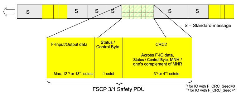
F-IO Data — the actual safety process data: digital inputs from a safety sensor, digital outputs to a safety actuator, or analog values with qualifier bytes. Maximum 12 octets for F_CRC_Seed=0, 13 octets for F_CRC_Seed=1.
Status/Control Byte — one byte with 8 bits that carry protocol management information between the F-Host and F-Device. See decoded bit tables below.
CRC2 — 3 octets (24 bits) for F_CRC_Seed=0, 4 octets (32 bits) for F_CRC_Seed=1. Covers everything above plus the MonitoringNumber.
The total overhead per F-Device is just 4 or 5 bytes per PROFIBUS/PROFINET cycle. This is why PROFIsafe can coexist with standard I/O on the same network without significant performance impact.
Status Byte: Decoded Bit by Bit
The Status Byte travels from the F-Device to the F-Host in every safety PDU.
| Bit | Signal Name | Meaning When SET |
|---|---|---|
| 0 | iPar_OK | F-Device has new iParameter values assigned — ready to resume data exchange |
| 1 | Device_Fault (F_Passivation=0) | F-Device cannot guarantee safety integrity of its process data — fail-safe values being sent |
| 1 | ChF_Ack_Req (F_Passivation=1) | At least one channel fault was cleared — operator acknowledgment required before resuming |
| 2 | CE_CRC | F-Device detected a CRC error or MonitoringNumber error in received data |
| 3 | WD_timeout | F-Device watchdog time exceeded — communication fault |
| 4 | FV_activated | Fail-safe values are currently being transmitted (outputs zeroed / inputs reported as 0) |
| 5 | Toggle_d | Device-side Toggle Bit — edge (0→1 or 1→0) signals MNR change to F-Host |
| 6 | cons_nr_R | F-Device has reset its MonitoringNumber |
| 7 | Reserved (0) | Reserved for future use; also used for loop-back detection in F_CRC_Seed=0 mode |
The most important bits in practice:
- Bit 1 (Device_Fault) going HIGH is the primary safety event — the F-Device has detected something wrong and is reporting it. The controller must respond by entering its fail-safe state.
- Bit 4 (FV_activated) HIGH means all safety outputs are currently zeroed. The machine cannot operate in this state.
- Bit 2 (CE_CRC) going HIGH repeatedly indicates a communication quality problem — possible EMC issue or network fault worth investigating.
Control Byte: Decoded Bit by Bit
The Control Byte travels from the F-Host to the F-Device in every safety PDU.
| Bit | Signal Name | Meaning When SET |
|---|---|---|
| 0 | iPar_EN | F-Host is requesting new iParameter assignment — F-Device should accept iParameters |
| 1 | OA_Req | Operator acknowledgment signal — F-Device should indicate request locally (e.g., via LED) |
| 2 | R_cons_nr | F-Host detected an error — reset MonitoringNumber in F-Device |
| 3 | Use_TO2 | “Configure in Run” active — extend watchdog time by secondary watchdog (F_WD_Time_2) |
| 4 | activate_FV | Force F-Device outputs to fail-safe values (0) |
| 5 | Toggle_h | Host-side Toggle Bit — edge signals MNR change to F-Device |
| 6 | ChF_Ack | Operator has acknowledged a cleared channel fault — resume normal operation |
| 7 | Loopcheck (F_CRC_Seed=0) | Always set to 1 — if F-Device echoes 1 back, a loop-back is detected |
| 7 | Reserved 0 (F_CRC_Seed=1) | Always 0 in current release |
Key control bits for engineers:
- Bit 4 (activate_FV) is how the safety controller forces an F-Device to its safe state from the application program.
- Bit 3 (Use_TO2) gives the system extra time during planned maintenance or hot reconfiguration without triggering a spurious watchdog trip.
- Bit 2 (R_cons_nr) resets the MonitoringNumber — the F-Host sends this after detecting a communication error, forcing a clean resynchronization of the MNR between both sides.
F-Parameters: The Safety Configuration
F-Parameters are the configuration data that define each PROFIsafe safety relationship. They are generated by the engineering tool, stored in the F-Host, and transmitted to the F-Device during startup. Any mismatch between stored and expected F-Parameters causes a startup failure.
| F-Parameter | Description |
|---|---|
| F_Source_Address | Source address (Codename component) — uniquely identifies the F-Host in this relationship |
| F_Dest_Address | Destination address (Codename component) — uniquely identifies the F-Device |
| F_WD_Time | Watchdog time in ms — primary timeout for both F-Host and F-Device |
| F_WD_Time_2 | Secondary watchdog time — extension used during “Configure in Run” |
| F_SIL | Target SIL for this communication relationship (SIL1, SIL2, or SIL3) |
| F_CRC_Length | Expected CRC length (2 = 3 octets, 3 = 4 octets) |
| F_CRC_Seed | CRC mode: 0 = 24-bit MNR counter, 1 = 32-bit Codename-based sequence |
| F_Passivation | 0 = whole-device passivation, 1 = channel-granular passivation |
| F_iPar_CRC | CRC across iParameters — integrity check for device-specific safety parameters |
| F_Par_CRC | CRC across all F-Parameters — integrity check for the F-Parameter block itself |
The Codename is derived from the combination of F_Source_Address and F_Dest_Address. It uniquely identifies the 1:1 safety communication relationship between one F-Host driver instance and one F-Device. Even if addresses are unique on a network, the Codename ensures that a message intended for F-Device A cannot be accepted by F-Device B.
The F_Par_CRC is a 16-bit CRC calculated across all F-Parameters. It is transmitted with the F-Parameters during startup and also encoded into the CRC2 seed value. This means the F-Parameters are implicitly verified in every cyclic safety PDU — not just at startup.
SIL and PL Ratings
PROFIsafe is rated for:
- SIL 3 (Safety Integrity Level 3) per IEC 61508
- PL e (Performance Level e) per ISO 13849-1
- Category 4 per EN 954-1 (legacy standard)
These are the highest functional safety levels in their respective standards. SIL 3 requires a probability of dangerous failure on demand (PFDavg) of between 10⁻⁴ and 10⁻³ for low-demand applications, and a probability of dangerous failure per hour (PFH) of between 10⁻⁸ and 10⁻⁷ for high-demand/continuous mode.
The PROFIsafe communication layer’s contribution to system PFH is extremely small — approximately 10⁻⁹ dangerous failures per hour (one undetected error every ~114,000 years at a 1 ms cycle time). This allows the communication layer to be essentially removed from the safety budget calculation for most applications.
Critical distinction: SIL 3 for the PROFIsafe communication layer does not automatically mean the overall system is SIL 3. The final SIL of the system depends on:
- The SIL capability of the F-Host (safety controller / F-CPU)
- The SIL capability of each F-Device (safety sensor or actuator)
- The PROFIsafe communication layer
- The application software (F-Program) and its programming
All four must be SIL 3 capable for the system to claim SIL 3. Implementing the PROFIsafe protocol in a standard (non-safety-rated) device does not make it an F-Device.
F-Host and F-Device Architecture
F-Host (Safety Controller)
The F-Host is the active side of a PROFIsafe relationship — typically a Safety PLC (F-CPU) or a safety I/O controller. Its responsibilities:
- Maintains an F-driver instance for each F-Device in its safety system
- Generates the Control Byte and CRC2 for every outgoing safety PDU
- Verifies the Status Byte and CRC2 of every incoming safety PDU
- Manages the MonitoringNumber and watchdog timer for each relationship
- Executes the F-Program — the safety application program that processes F-IO data
- Transmits F-Parameters to F-Devices during startup
- Manages iParameter assignment and iPar-Server
One F-Host can manage a mix of standard devices (no PROFIsafe) and F-Devices (with PROFIsafe) on the same network simultaneously.
F-Device (Safety Field Device)
The F-Device is the passive side — a safety sensor, safety actuator, safety remote I/O module, or drive with integrated safety. Its responsibilities:
- Receives and verifies the Control Byte and CRC2 of every incoming safety PDU
- Generates the Status Byte and CRC2 for every outgoing safety PDU
- Maintains its own MonitoringNumber and watchdog timer
- Reports device faults via the Device_Fault bit
- Accepts iParameters when iPar_EN is set
- Goes to its fail-safe state (outputs to 0) when watchdog expires or CRC fails
Shared F-Inputs are not permitted. Each F-Device can only have a 1:1 relationship with one F-Host at a time. Standard PROFINET shared device / shared input features are explicitly excluded for safety channels.
Modular F-Devices and F-Modules
A modular F-Device (like a safety remote I/O with multiple slots) can contain multiple F-Modules, each with its own FSCP 3/1 communication relationship. Each F-Module has its own safety PDU in the PROFINET IO data, its own Status/Control Byte, and its own CRC2. The head station (Device Access Point, DAP) acts as a gateway and is part of the black channel.
Channel-Granular Passivation
When F_Passivation = 1, an F-Module can passivate individual channels rather than the entire device. If channel 3 of an 8-channel safety input module fails:
- Without channel-granular passivation: all 8 channels go to fail-safe values
- With channel-granular passivation: only channel 3 goes to fail-safe; channels 1, 2, 4–8 continue operating
This significantly improves availability in large safety systems — a single channel fault does not take down the entire F-Module.
PROFIsafe Startup Sequence
Understanding the startup sequence is essential for commissioning and for interpreting PLC diagnostic messages.
1. Standard communication established — the F-Host and F-Device complete their normal PROFIBUS/PROFINET initialization (parameterization, configuration check, data exchange start).
2. F-Parameter transmission — the F-Host sends the F-Parameter block (including F_Source_Address, F_Dest_Address, F_WD_Time, F_SIL, F_CRC_Seed, F_iPar_CRC, F_Par_CRC) to the F-Device via acyclic record data (PROFINET) or DP-V1 acyclic (PROFIBUS).
3. F-Parameter verification — the F-Device checks:
- F_Dest_Address matches its own configured address
- F_Par_CRC is correct (F-Parameters are internally consistent)
- F_SIL does not exceed the device’s own SIL capability
- F_CRC_Length matches the expected CRC format
If any check fails, the F-Device reports a diagnosis message (see diagnosis codes below) and does not enter safety data exchange.
4. iParameter assignment (if required) — for devices with device-specific safety parameters (iParameters, e.g., the protection zone coordinates of a laser scanner), the F-Host signals iPar_EN = 1. The F-Device loads its iParameters and confirms with iPar_OK = 1.
5. Safety data exchange — both sides initialize their MonitoringNumbers and begin cyclic exchange of safety PDUs. The fail-safe values (FV = 0) are sent until the MNR synchronization is established, then real process values are exchanged.
PROFIsafe Diagnosis Codes
When a PROFIsafe fault occurs, the F-Device reports a diagnosis message to the F-Host via the standard PROFINET/PROFIBUS channel-related diagnosis mechanism. The ChannelErrorType field contains a PROFIsafe-specific code:
| Hex Code | Decimal | Diagnosis |
|---|---|---|
| 0x0040 | 64 | Mismatch of safety destination address (F_Dest_Address) |
| 0x0041 | 65 | Safety destination address not valid |
| 0x0042 | 66 | Safety source address not valid or mismatch |
| 0x0043 | 67 | Safety watchdog time value is 0 ms |
| 0x0044 | 68 | F_SIL parameter exceeds SIL from device application |
| 0x0045 | 69 | F_CRC_Length does not match generated values |
| 0x0046 | 70 | Version of F-Parameter set incorrect |
| 0x0047 | 71 | Data inconsistent in received F-Parameter block (CRC1 error) |
| 0x0048 | 72 | Device-specific or unspecified diagnosis — see device manual |
| 0x0049 | 73 | Save iParameter watchdog time exceeded |
| 0x004A | 74 | Restore iParameter watchdog time exceeded |
| 0x004B | 75 | Inconsistent iParameters (iPar_CRC error) |
| 0x004C | 76 | F_Block_ID not supported |
| 0x004D | 77 | Transmission error: data inconsistent (CRC2 error) |
| 0x004E | 78 | Transmission error: timeout (F_WD_Time or F_WD_Time_2 elapsed) |
Most common in practice:
Code 0x0040 / 64 — Destination address mismatch. The F_Dest_Address configured in the F-Host does not match what the F-Device has configured. Check F-Parameter assignment in the engineering tool and verify the physical device address.
Code 0x0047 / 71 — CRC1 error. The F-Parameter block received by the F-Device has a CRC error — the block was corrupted in transit or there is a version mismatch between the engineering tool configuration and the device firmware. Re-download the F-Parameters.
Code 0x004B / 75 — iPar_CRC error. The iParameters stored in the F-Device (safety-relevant device-specific settings such as protection zones) do not match what the F-Host expects. The F_iPar_CRC in the F-Parameter block does not match the CRC of the stored iParameters. Requires re-parameterization of device-specific safety settings.
Code 0x004D / 77 — CRC2 error. Data corruption detected in the cyclic safety data. Isolated occurrences during startup are normal (MNR resynchronization). Persistent CRC2 errors during operation indicate EMC problems or a failing device.
Code 0x004E / 78 — Timeout. The watchdog expired. Either the network communication was interrupted, the master stopped polling the device, or the watchdog time is configured too short for the actual network load.
Safety Function Response Time
The Safety Function Response Time (SFRT) is defined in IEC 61784-3-3 as the worst-case elapsed time from actuation of a safety sensor until its safety actuator reaches the safe state, including the possibility of errors in the communication system.
For a basic PROFIsafe system (one F-Host, one F-sensor, one F-actuator):
SFRT ≤ F_WD_Time (sensor) + processing time (F-Host) + F_WD_Time (actuator)
In practice, for a PROFINET-based PROFIsafe system with 1 ms cycle time and 100 ms watchdog times: SFRT ≈ 200–300 ms including the controller processing. For PROFIBUS-based systems the cycle time is longer, which increases SFRT.
The watchdog time (F_WD_Time) is the key design parameter. It must be:
- Long enough that normal network jitter and scheduling variation never triggers a false watchdog timeout
- Short enough that the SFRT meets the required safety response time for the application
Typical guidance (PROFIBUS DP at 12 Mbit/s):
- F_WD_Time ≥ 3 × bus cycle time (to allow for retries and jitter)
- Minimum recommended: 10 ms
Typical guidance (PROFINET with 1 ms update rate):
- F_WD_Time ≥ 3 × 1 ms = 3 ms minimum
- Practical minimum: 10–20 ms to avoid nuisance trips
PROFIsafe on Wireless Networks
IEC 61784-3-3 explicitly permits PROFIsafe over wireless networks (IEEE 802.11 Wi-Fi and IEEE 802.15.1 Bluetooth). The black channel principle means wireless links are treated the same as any other transport — PROFIsafe’s safety measures work regardless.
Restrictions apply:
- Codenames (F_Source_Address, F_Dest_Address) must be unique across the entire wireless island, including across routers
- Single-port routers are not permitted
- The wireless bridge propagation delay contributes to SFRT and must be accounted for in the watchdog time calculation
- The watchdog time must be large enough to absorb the additional latency and jitter introduced by Wi-Fi protocol retries
In practice, PROFIsafe over Wi-Fi is used for mobile equipment (AGVs, collaborative robots, handheld tools) where hardwired safety connections are impractical.
PROFIsafe vs. Other Safety Protocols
| Feature | PROFIsafe | CIP Safety | FSoE (EtherCAT) |
|---|---|---|---|
| Standard | IEC 61784-3-3 | IEC 61784-3-2 | IEC 61784-3-12 |
| Transport | PROFIBUS, PROFINET | EtherNet/IP, DeviceNet | EtherCAT |
| Max SIL | SIL 3 | SIL 3 | SIL 3 |
| Max PL | PL e | PL e | PL e |
| Black channel | Yes | Yes | Yes |
| Wireless support | Yes (native) | Yes | Limited |
| Shared inputs | No | Limited | No |
| Installed base | Largest (millions of nodes) | Large | Growing |
PROFIsafe has the largest installed base of any industrial safety protocol, reflecting the dominant market position of PROFIBUS and PROFINET.
Key Numbers at a Glance
| Parameter | Value |
|---|---|
| IEC Standard | IEC 61784-3-3:2016 (FSCP 3/1) |
| Maximum SIL | SIL 3 (IEC 61508) |
| Maximum PL | PL e (ISO 13849-1) |
| Communication relationship | 1:1 (F-Host to F-Device) |
| Max F-IO data per PDU | 12 octets (F_CRC_Seed=0), 13 octets (F_CRC_Seed=1) |
| Status/Control Byte | 1 octet |
| CRC2 size | 3 octets (24-bit, F_CRC_Seed=0), 4 octets (32-bit, F_CRC_Seed=1) |
| CRC polynomial (24-bit) | 0x5D6DCB |
| CRC polynomial (32-bit) | 0xF4ACFB13 |
| MonitoringNumber (F_CRC_Seed=0) | 24-bit counter, 1 to 0xFFFFFF |
| MonitoringNumber (F_CRC_Seed=1) | 32-bit Codename-based random sequence |
| Residual error rate | < 10⁻⁹ per hour (communication layer only) |
| Compatible transports | PROFIBUS DP, PROFIBUS PA, PROFINET, fiber optic, wireless |
| Shared inputs permitted | No |
Summary
PROFIsafe solves the fundamental problem of running safety communication over a standard industrial network: the network cannot be trusted, so the safety protocol trusts nothing and verifies everything independently.
Its four measures — MonitoringNumber, watchdog with acknowledgment, Codename authentication, and CRC2 data integrity — cover every credible failure mode in a fieldbus communication system. The black channel principle means the approach is transport-agnostic, working identically over PROFIBUS, PROFINET, fiber, copper, and wireless.
The Safety PDU is small (maximum 17–18 bytes total), the overhead is minimal, and the protocol integrates cleanly with standard PROFIBUS and PROFINET infrastructure. Standard and safety devices coexist on the same network, with the same cables, the same switches, and the same controller.
For safety engineers working with PROFIBUS or PROFINET systems, PROFIsafe is the de facto choice for functional safety communication — and understanding its mechanics at the protocol level is essential for correct engineering, commissioning, and troubleshooting.