In industrial automation, Modbus over RS-485 is still one of the most popular and reliable ways to connect programmable logic controllers (PLCs), sensors, meters, and field devices.
One key parameter that determines how well this network performs is the communication frequency. this is also called the baud rate. It defines how fast data is transmitted between Modbus master and slave devices and directly affects signal integrity, cable length, and network reliability.
This article explains what Modbus over RS485 communication frequency means, how it works, recommended baud rates, and how to choose the right settings for your system.
Table of Contents
What is Modbus over RS485?
Modbus is a serial communication protocol developed by Modicon (now Schneider Electric) in 1979.
When transmitted over RS-485, it becomes Modbus RTU (Remote Terminal Unit) — a half-duplex, differential signaling system designed for robust industrial data transfer.
- RS-485 serves as the physical layer (hardware wiring).
- Modbus RTU defines the data protocol (how information is formatted and interpreted).
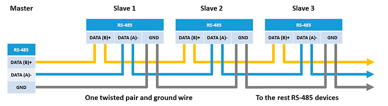
In a Modbus over RS-485 system, devices are connected in a daisy-chain configuration, not a star topology, to maintain balanced signal paths and proper termination.
Understanding Modbus Communication Frequency
The communication frequency in a Modbus over RS-485 system refers to how fast bits are transmitted on the bus — measured in bits per second (bps), or baud rate.
Common Modbus devices support speeds from 1,200 bps up to 115,200 bps, and sometimes higher in modern PLCs.
Each bit of data corresponds to one signal transition on the RS-485 line, so a baud rate of 9,600 bps means 9,600 bit transitions per second — effectively a 9.6 kHz signal frequency.
Common Modbus RS485 Baud Rates
| Baud Rate (bps) | Equivalent Frequency (Hz) | Typical Application |
|---|---|---|
| 1200 | 1.2 kHz | Legacy systems, very long cable runs |
| 2400 | 2.4 kHz | Low-speed control devices |
| 4800 | 4.8 kHz | Utility systems, noise-prone areas |
| 9600 | 9.6 kHz | Default setting for most Modbus devices |
| 19200 | 19.2 kHz | General-purpose automation |
| 38400 | 38.4 kHz | Modern PLCs, stable environments |
| 57600 – 115200 | 57.6–115.2 kHz | High-speed data acquisition systems |
Most Modbus RTU devices default to 9600 bps, 8 data bits, no parity, 1 stop bit (8N1).
Frequency vs Cable Length
As communication frequency (baud rate) increases, the maximum reliable cable length decreases due to signal attenuation and electromagnetic interference.
| Baud Rate (bps) | Approx. Max Cable Length (m) | Comments |
|---|---|---|
| 1200 | 1200+ | Very long distance, low data rate |
| 4800 | 1000 | Stable for most field environments |
| 9600 | 1200 | Standard, recommended default |
| 19200 | 600 | Moderate distances |
| 38400 | 300 | Shorter cable runs |
| 115200 | 100 | Requires excellent shielding and termination |
Rule of Thumb:
Double the baud rate → halve the cable length for reliable communication.
Choosing the Right Baud Rate for Your Network
The ideal baud rate depends on distance, device count, cable quality, and noise level.
| Condition | Recommended Baud Rate |
|---|---|
| Long cable runs (>500 m) | 9600 or 19200 bps |
| Noisy industrial environments | 4800–9600 bps |
| Short, shielded networks | 38400–57600 bps |
| Lab or cabinet setups | 57600–115200 bps |
Example:
A water treatment plant with 15 Modbus RTU sensors on a 500 m RS-485 line typically uses 9600 bps for reliability.
Example: Modbus RTU Timing Calculation
Let’s calculate an example timing at 9600 bps:
- Each bit = 1 / 9600 ≈ 104 µs
- Each byte = 11 bits (1 start + 8 data + 1 parity + 1 stop) → 1.14 ms
- A Modbus RTU frame of 8 bytes ≈ 9.1 ms
Adding inter-frame delays (~3.5 character times) → 12–15 ms per message.
That means roughly 60–80 Modbus messages per second are possible at 9600 bps — sufficient for most control applications.
Best Practices for Stable Modbus over RS485 Communication
To ensure consistent Modbus RTU performance at any frequency:
- Use twisted-pair, shielded RS-485 cable (120 Ω impedance).
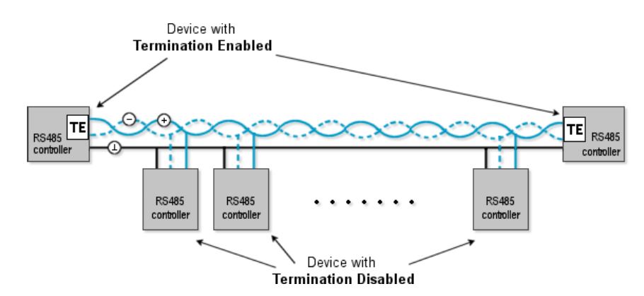
- Terminate both ends with 120 Ω resistors.
- Add bias resistors to maintain idle line voltage.
- Keep stub lengths < 1 meter from main bus line.
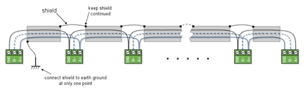
- Ground the shield at one end only to avoid ground loops.
- Set identical baud rate, parity, and stop bits across all devices.
- Avoid unnecessary baud increases — stability is more important than speed.
Conclusion
The Modbus over RS485 communication frequency — or baud rate — directly impacts the speed, reliability, and range of your industrial network.
- Use lower baud rates (9600–19200 bps) for long cables and high noise environments.
- Use higher baud rates (38400–115200 bps) for short, shielded setups where quick response is needed.
Choosing the right communication frequency ensures stable Modbus RTU operation, accurate data transfer, and minimal transmission errors — keeping your automation system running smoothly.