
Industrial communication networks are very different from office or IT networks. In factories, substations, water plants, and process industries, communication is part of the control system itself. If data stops flowing, machines can stop, processes can become unstable, alarms may be delayed, and safety can be affected.
Because of this, industrial networks must be highly available, predictable, and fast to recover from failures. One of the most common ways to achieve this reliability is by using network redundancy. However, redundancy introduces its own problem: Ethernet loops.
The Media Redundancy Protocol (MRP) was created specifically to solve this problem in industrial Ethernet ring networks. It provides fast, deterministic recovery from failures while keeping the network simple and stable.
This article explains MRP in a clear way, while still going deep into the technical details. It covers how MRP works, why it exists, how it behaves during failures, where it fits best, and how it compares to other redundancy methods used in industrial communication networks.
Table of Contents
Why Redundancy Is Critical in Industrial Networks
In industrial environments, Ethernet networks are used for tasks such as:
- PLC and controller communication
- SCADA and HMI data exchange
- Distributed I/O traffic
- Time-critical control signals
- Monitoring, alarms, and diagnostics
Even a short interruption can cause serious problems:
- Loss of controller communication
- Frozen operator screens
- Missed or delayed alarms
- Control loops switching to fallback modes
- Production downtime
To reduce the risk of a single cable or switch failure, industrial networks are often built with redundant physical paths. Ring topologies are especially popular because they are simple to wire and provide natural redundancy.
But Ethernet does not allow loops by default. Without control, loops cause broadcast storms and network collapse. This is where redundancy protocols are required.
What Is Media Redundancy Protocol (MRP)?
Media Redundancy Protocol (MRP) is a Layer 2 protocol designed to protect Ethernet ring topologies in industrial networks.
MRP ensures that:
- The ring operates without loops during normal conditions
- A single failure does not interrupt communication
- Recovery happens quickly and predictably
- Network behavior remains simple and deterministic
MRP is standardized in IEC 62439-2, which focuses on high-availability automation networks. Unlike general IT protocols, MRP was designed from the beginning for industrial use.
Basic Idea Behind Media Redundancy Protocol
The core idea of MRP is very simple:
- The physical network is a ring
- Logically, one link in the ring is blocked
- All traffic flows in one direction around the ring
- If a failure occurs, the blocked link is unblocked
- Communication continues using the remaining path
This approach avoids loops while keeping a backup path available at all times.
Typical MRP Ring Topology
An MRP ring consists of:
- Multiple Ethernet devices connected in a closed loop
- Each device has exactly two ring ports
- One device acts as the ring manager
- All other devices act as ring clients
Under normal operation:
- One port on the ring manager blocks traffic
- The ring behaves like a simple line
- All devices can communicate normally
Key Roles in MRP
Media Redundancy Manager (MRM)
The Media Redundancy Manager is the control point of the ring.
Its responsibilities include:
- Monitoring the health of the ring
- Sending test messages around the ring
- Detecting breaks or failures
- Opening or closing the blocked port
Only one manager is active in a ring at a time.
Media Redundancy Clients (MRC)
Media Redundancy Clients are the normal ring devices.
Their responsibilities include:
- Forwarding Ethernet traffic
- Passing MRP control messages
- Reporting link status changes
- Following the instructions of the manager
Clients do not make topology decisions themselves.
How MRP Works During Normal Operation
During normal operation, the MRP ring is intact.
The manager:
- Blocks one of its ring ports
- Sends periodic test frames into the ring
- Expects these frames to return through the unblocked path
If the manager receives its own test frame back, it knows the ring is complete.
This constant monitoring allows MRP to detect failures very quickly.
How Media Redundancy Protocol Detects Failures
Failures in an industrial network usually happen because of:
- Cable damage
- Connector problems
- Switch or device power loss
- Environmental stress (vibration, heat, moisture)
MRP detects failures in two main ways:
- Link status detection
If a port goes down physically, the device immediately knows. - Test frame timeout
If test frames do not return within the expected time, the ring is assumed to be broken.
Because MRP operates at Layer 2 and uses short control frames, detection is very fast.
What Happens When a Failure Occurs
When a single failure occurs in the ring:
- The ring is physically broken
- Test frames no longer return to the manager
- The manager detects the failure
- The manager unblocks its previously blocked port
- Traffic is rerouted around the remaining path
The ring becomes a line, but all devices remain connected.
MRP Recovery Time
One of the main reasons MRP is popular is its fast recovery time.
Typical characteristics:
- Recovery times below 200 ms are common
- Smaller rings can recover even faster
- Recovery time depends on:
- Number of devices
- Test frame interval
- Device performance
This speed is sufficient for many industrial control applications, including factory automation and SCADA systems.
Deterministic Behavior of MRP
A key advantage of MRP is determinism.
Unlike general-purpose protocols:
- There is no complex topology calculation
- No root bridge election
- No path cost comparison
- No unpredictable reconvergence
The behavior of the ring is simple and well defined:
- One manager
- One blocked port
- One alternate path
This makes MRP easier to design, test, and troubleshoot.
Media Redundancy Protocol and Traffic Flow
MRP itself does not modify or prioritize application traffic. It simply controls whether frames are forwarded or blocked on specific ports.
This means:
- All standard Ethernet traffic is supported
- Industrial protocols can run unchanged
- Multicast and broadcast traffic behave predictably
- No application awareness is required
MRP works transparently below the application layer.
MRP Ring Sizes and Limits
MRP is designed for moderate-sized rings, which are common in industrial installations.
Typical considerations include:
- Dozens of devices per ring are common
- Very large rings increase recovery time
- Multiple rings can be interconnected if needed
For very large or complex networks, multiple smaller rings are often preferred.
MRP Interconnection Between Rings
In larger installations, it is common to have:
- Several MRP rings
- Interconnections between rings
- Hierarchical network structures
MRP supports controlled interconnection mechanisms that allow rings to be connected without creating loops, while still maintaining fast recovery behavior within each ring.
MRP and Network Stability
MRP improves stability in several ways:
- No topology flapping
- Clear responsibility for control decisions
- Minimal control traffic
- Fast and predictable transitions
This stability is especially important in industrial systems where unexpected network behavior can cause control issues.
Advantages of MRP in Industrial Communication Networks
MRP offers several important advantages:
- Fast recovery suitable for automation systems
- Simple ring topology that is easy to design
- Deterministic behavior with predictable results
- Low configuration effort
- Standardized protocol designed for industry
These features make MRP a strong choice for many industrial environments.
Limitations of MRP
Despite its strengths, MRP is not perfect.
Important limitations include:
- Designed only for ring topologies
- Does not provide seamless, zero-loss recovery
- Single manager is a logical control point
- Not suitable for complex mesh networks
For applications requiring zero packet loss or sub-millisecond recovery, other solutions may be required.
Typical Use Cases for MRP
MRP is commonly used in:
- Factory automation networks
- Production line communication
- Conveyor and material handling systems
- Distributed I/O networks
- SCADA field networks
- Water and wastewater plants
- Power distribution substations
These applications value fast recovery, simplicity, and reliability.
MRP Compared to Other Redundancy Methods
MRP vs Traditional Spanning Tree
Traditional spanning tree protocols:
- Are designed for office networks
- Have slower recovery
- Are less deterministic
MRP is faster, simpler, and better suited for industrial rings.
MRP vs Seamless Redundancy
Seamless redundancy methods provide:
- Zero packet loss
- No switchover time
However, they require:
- Duplicate networks
- More hardware
- Higher cost
MRP offers a balanced solution where brief interruptions are acceptable.
Design Best Practices for MRP Networks
To get the best results from MRP:
- Keep ring sizes reasonable
- Clearly define the ring manager
- Use industrial-grade switches
- Avoid mixing redundancy protocols in the same ring
- Test failure scenarios during commissioning
- Document the ring topology and configuration
Good planning is essential for predictable behavior.
Troubleshooting Media Redundancy Protocol Networks
When issues occur, common checks include:
- Verifying ring continuity
- Checking manager status
- Reviewing link state counters
- Monitoring recovery events
- Inspecting cables and connectors
Because MRP behavior is simple, troubleshooting is usually straightforward.
MRP and Long-Term Reliability
Industrial networks are expected to run for many years.
MRP supports long-term reliability by:
- Minimizing control traffic
- Avoiding unnecessary topology changes
- Handling failures automatically
- Reducing operator intervention
This makes it well suited for harsh industrial environments.
When to Choose Media Redundancy Protocol
MRP is a good choice when:
- Ring topology is preferred
- Fast recovery is needed
- Network simplicity is important
- Deterministic behavior is required
- Multi-vendor compatibility is desired
It is often chosen as the default redundancy method for industrial Ethernet rings.
When MRP May Not Be Enough
MRP may not be sufficient when:
- Zero packet loss is mandatory
- Recovery must be sub-millisecond
- Complex mesh topologies are required
- Redundant controllers require parallel paths
In such cases, more advanced redundancy methods may be needed.
The Role of MRP in Modern Industrial Networks
Even as industrial networks evolve, MRP remains relevant.
Reasons include:
- Continued use of ring topologies
- Need for simple and robust designs
- Long equipment life cycles
- Proven reliability in the field
MRP fits well into modern automation architectures that value stability over complexity.
Practical Example: Two MRP Rings with Redundant Interconnection
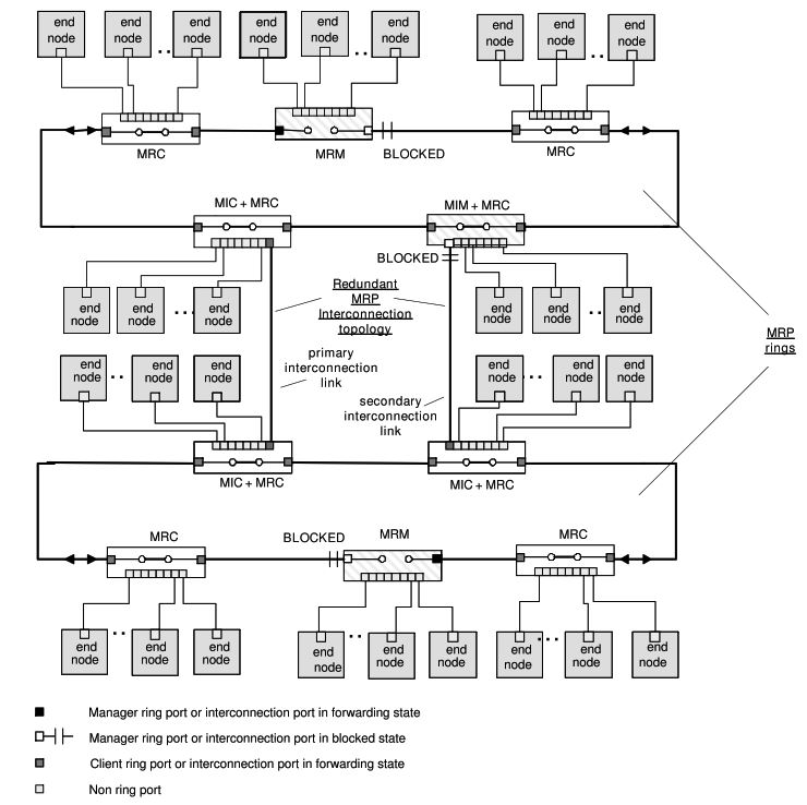
The diagram shows two independent MRP rings that are redundantly interconnected to improve availability while still avoiding Ethernet loops.
Let’s break it down step by step.
1. What You Are Looking At (Big Picture)
- There are two separate MRP rings
- Upper ring
- Lower ring
- Each ring has:
- One MRM (Media Redundancy Manager)
- Multiple MRCs (Media Redundancy Clients)
- End devices (PLCs, I/O, drives, relays, HMIs, etc.)
- The two rings are connected together using MRP Interconnection:
- One primary interconnection link
- One secondary (redundant) interconnection link
This design is common in:
- Large factories
- Substations
- Water / wastewater plants
- Long production lines split into zones
2. Normal Operation (No Failures)
Inside Each Ring
- The MRM blocks one ring port
- This prevents a loop inside the ring
- Traffic flows normally in one direction
You can see this in the diagram:
- Each ring has a BLOCKED label at the manager
Result:
- Each ring behaves like a simple line
- All devices can communicate
Between the Two Rings
- The primary interconnection link is active
- The secondary interconnection link is blocked
This is critical:
- Only one interconnection path is forwarding
- The second one exists purely as backup
- No loop is created between the rings
Result:
- Upper ring and lower ring can exchange data
- SCADA, controllers, and servers see a single logical network
3. Roles of Special Devices in the Diagram
MIC + MRC
These devices act as:
- Normal ring clients and
- Interconnection clients
They:
- Forward traffic between rings
- Follow instructions from the interconnection manager
- Do not decide topology on their own
MIM + MRC
This device is the interconnection manager.
It:
- Controls which interconnection link is blocked
- Monitors the health of inter-ring links
- Ensures only one interconnection path is active
Think of it as:
“The traffic controller between the two rings”
4. Failure Scenario 1: Cable Break Inside One Ring
Example
A cable breaks in the upper ring.
What Happens
- The upper ring MRM stops receiving test frames
- The MRM detects a ring break
- The blocked ring port is unblocked
- Traffic reroutes the other way around the ring
Result
- Upper ring stays operational
- Lower ring is unaffected
- Interconnection remains unchanged
- Recovery typically < 200 ms
This is classic MRP ring protection.
5. Failure Scenario 2: Failure of Primary Interconnection Link
Example
The primary interconnection cable between the rings is cut.
What Happens
- The MIM detects loss of the primary link
- The previously blocked secondary interconnection link is unblocked
- Traffic switches to the secondary path
Result
- Upper and lower rings remain connected
- No loop is created
- Communication continues with a short interruption
This is the key benefit of MRP interconnection redundancy.
6. Failure Scenario 3: Device Failure at Interconnection Point
Example
The switch acting as MIC + MRC fails.
What Happens
- The interconnection path through that device is lost
- The MIM detects topology change
- If an alternate interconnection path exists, it is activated
Result
- Rings may still communicate depending on topology
- Local ring protection continues to function
- Fault is isolated to one area
7. Why This Design Is Used in Real Plants
This topology is used when:
- A single ring is not large enough
- Different plant areas must be isolated
- You want controlled redundancy instead of a flat network
- Maintenance needs to be localized
- Faults must not propagate across the entire plant
Typical examples:
- One ring per production line
- One ring per voltage level in substations
- One ring per process area
8. Key Advantages of This MRP Design
Fast Recovery
- Ring failures: typically < 200 ms
- Interconnection failures: predictable and controlled
Deterministic Behavior
- No spanning tree recalculations
- No path hunting
- No unstable topology
Fault Isolation
- A failure in one ring does not collapse the whole network
- Troubleshooting is simpler
Industrial Simplicity
- Clear manager roles
- Easy to document
- Easy to test during FAT and SAT
9. Important Engineering Rules (Very Important)
When building this topology in real life:
- Never allow two interconnection links to forward at the same time
- Only one MRM per ring
- Only one MIM per interconnection domain
- Do not mix RSTP inside an MRP ring
- Use industrial managed switches only
- Always test:
- Ring break
- Interconnection break
- Power loss of manager devices
10. Simple Real-World Summary
Think of this design like:
- Two circular roads (rings)
- Each has one traffic controller
- There are two bridges between the roads
- Only one bridge is open at a time
- If any road or bridge breaks, traffic is quickly redirected
That is exactly what the diagram represents.
Conclusion
Media Redundancy Protocol (MRP) is a purpose-built solution for protecting Ethernet ring networks in industrial communication systems. It addresses the unique requirements of automation networks by combining fast recovery, deterministic behavior, and simple operation.
By blocking a single link during normal operation and rapidly restoring it during failures, MRP ensures continuous communication with minimal disruption. While it does not provide seamless redundancy, its balance of speed, simplicity, and reliability makes it one of the most widely used redundancy mechanisms in industrial Ethernet networks.
When properly designed and implemented, Media Redundancy Protocol provides a strong foundation for reliable industrial communication, supporting stable control, safe operation, and long-term system availability.