The Application Service Data Unit (ASDU) is the core of the IEC 60870-5-104 communication protocol. It defines how information is represented and exchanged between a controlling station (SCADA master) and controlled stations such as RTUs or IEDs.
If the Application Protocol Data Unit (APDU) is the message envelope, the ASDU is the payload — carrying the actual telemetry data, commands, and event details that keep power and industrial systems synchronized.
This article explains how the ASDU is structured, what each field represents, and how to interpret it when analyzing IEC 104 frames.
Table of Contents
The Role of the ASDU in IEC 104
In IEC 104, data travels inside TCP/IP packets, but the application layer follows the same logic as the older IEC 101 serial standard. That means the ASDU structure in both is identical — ensuring backward compatibility between legacy serial systems and modern Ethernet-based networks.
Each ASDU conveys a specific message type, such as a measurement, a status change, or a control command, and always includes contextual information like why the data was sent (Cause of Transmission) and where it came from (Common Address of ASDU).
The Basic ASDU Format
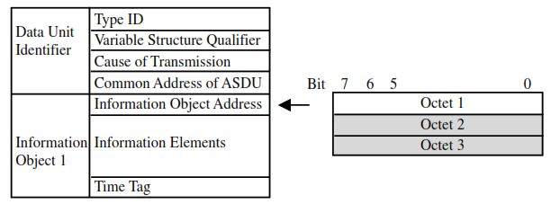
Below is a visual representation of the ASDU (Application Service Data Unit) structure as defined in IEC 60870-5-104. It shows how the Data Unit Identifier fields (Type ID, VSQ, COT, Common Address) are followed by one or more Information Objects, each containing its own address, data elements, and optional timestamp.
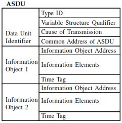
Explanation:
- The top portion, Data Unit Identifier, defines the context of the data.
- Each Information Object below carries the actual data values and optional time tags (CP24Time2a or CP56Time2a).
- Multiple information objects can be grouped within one ASDU if the Variable Structure Qualifier (VSQ) allows it.
Type Identification (Type ID)
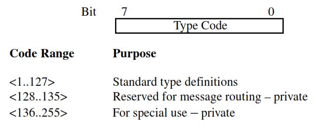
The Type ID (1 byte) defines what kind of data the ASDU contains.
Common examples include:
| Type ID | Mnemonic | Meaning |
|---|---|---|
| 1 | M_SP_NA_1 | Single-point information (no timestamp) |
| 3 | M_DP_NA_1 | Double-point information |
| 9 | M_ME_NA_1 | Measured value, normalized |
| 11 | M_ME_NC_1 | Measured value, short floating point |
| 45 | C_SC_NA_1 | Single command (control) |
| 100 | C_IC_NA_1 | Interrogation command |
| 103 | C_CS_NA_1 | Clock synchronization |
| 120–124 | F_FR–F_AF | File transfer and archive control |
The Type ID is the first clue Wireshark or any SCADA analyzer uses to decode the frame’s meaning.
Important Note:
The Type Identification (Type ID) applies to the entire ASDU — not to individual information objects. This means that if multiple information objects are contained in a single ASDU, they must all be of the same type. For example, an ASDU with Type ID = 9 (Measured Value, Normalized) can include several measurement objects, but not a mix of digital and analog data.
This ensures that the receiver interprets all data elements consistently and efficiently, reducing protocol overhead while maintaining integrity across grouped values.
Variable Structure Qualifier (VSQ)
The Variable Structure Qualifier (VSQ) is a single-octet field that determines how many information objects or elements are included in the ASDU and how they are addressed.
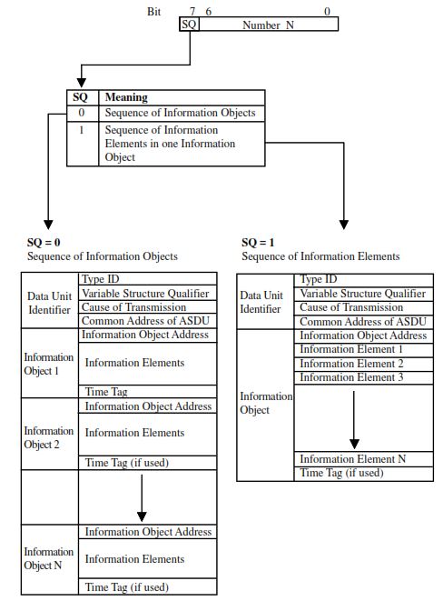
It consists of seven bits representing the number of objects or elements (N, range 1–127) and one bit (bit 7) that defines the structure type — whether multiple independent information objects are present, or a single information object contains several sequential elements.
Structure of the Variable Structure Qualifier
| Bit | Name | Meaning |
|---|---|---|
| 7 | SQ (Sequence Bit) | 0 = Sequence of information objects (each has its own address) 1 = Sequence of information elements under one base address |
| 6–0 | N | Number of information objects or elements (1–127) |
Understanding the Two Information Structures
| SQ | Structure Type | Explanation |
|---|---|---|
| SQ = 0 | Sequence of Information Objects | Each information object has its own address (IOA). Used when multiple, non-sequential points are reported together. |
| SQ = 1 | Sequence of Information Elements | A single base IOA is given; subsequent elements are assumed to have consecutive addresses (IOA, IOA+1, IOA+2, …). Used for block data such as analog arrays or counters. |
Cause of Transmission (COT)
Every ASDU (Application Service Data Unit) in IEC 60870-5-104 includes a field called the Cause of Transmission (COT). This field tells the receiving station why the message was generated — whether it was a spontaneous event, a response to a request, or a confirmation of a control command.
Understanding the COT is essential for correctly interpreting communication flows between controlling stations (masters) and controlled stations (RTUs/IEDs).
Structure of the Cause of Transmission Field
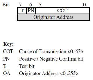
The COT field is a six-bit code, often extended to one or two octets, used to describe the reason for sending the ASDU.
In addition to the six main bits, there are two control flags and an optional originator address that further define message context.
Field Meaning
| Bit / Field | Description |
|---|---|
| Bits 0–5 | Six-bit COT code (0–63) that defines the cause or purpose of transmission. |
| Bit 6 (P/N) | Positive/Negative confirmation bit — indicates success or failure of a control command. |
| Bit 7 (T) | Test bit — set when the ASDU is generated for test purposes and not intended to change process state. |
| Originator Address | Optional (system-specific). Identifies the controlling station that generated the command, used in multi-master or dual-mode systems. |
How Each Bit Works
1. PN Bit (Positive/Negative Confirmation)
Used mainly with control commands. When the SCADA master issues a control (for example, “switch breaker ON”), the RTU mirrors that command back in the monitoring direction. If the PN bit = 0, the command executed successfully. If PN = 1, it indicates a negative confirmation, meaning the command failed or was rejected.
2. T Bit (Test)
When set = 1, it means the ASDU is generated only for testing transmission or device integrity and does not affect the actual process. For example, during communication link testing, messages carry the test bit to avoid triggering real outputs.
3. Originator Address
This field is optional and only used when multiple controlling stations exist on the same system. It allows a response or confirmation to be routed back to the specific master that issued the command. If the originator address = 0, it functions as the default address and the message is broadcast to all controlling stations.
COT Codes and Their Meanings
The following table lists the standard Cause of Transmission codes defined in IEC 60870-5-104.
Each ASDU Type ID supports only a subset of these codes relevant to its purpose.
| COT Code | Mnemonic | Meaning |
|---|---|---|
| 0 | — | Not used |
| 1 | PER | Periodic / Cyclic transmission |
| 2 | BGS | Background scan |
| 3 | SP | Spontaneous event |
| 4 | INIT | Initialization |
| 5 | REQ | Request / Requested |
| 6 | ACT | Activation |
| 7 | ACTCON | Activation confirmation |
| 8 | DEACT | Deactivation |
| 9 | DEACTCON | Deactivation confirmation |
| 10 | ACTTERM | Activation termination |
| 11 | RETREM | Return info — remote command |
| 12 | RETLOC | Return info — local command |
| 13 | FILE | File transfer |
| 14–19 | — | Reserved for future use |
| 20 | INT | Interrogated by station interrogation |
| 21–36 | INT G1–G16 | Interrogated by group (1–16) |
| 37 | CNT ALL | Requested by general counter request |
| 38–41 | CNT G1–G4 | Requested by group (1–4) counter request |
| 42–43 | — | Reserved |
| 44 | UNK-TID | Unknown Type Identification |
| 45 | UNK-COT | Unknown Cause of Transmission |
| 46 | UNK-CA | Unknown Common Address of ASDU |
| 47 | UNK-IOA | Unknown Information Object Address |
How COT Works in Practice
When a status change occurs in a field device:
- The RTU creates an ASDU with
COT = 3(Spontaneous). - It includes the Type ID corresponding to the signal (e.g., Type 1 = Single-Point Info).
- The SCADA master receives and logs the spontaneous event.
When the master sends a control command:
- It transmits an ASDU with
COT = 6(Activation). - The RTU responds with
COT = 7(Activation Confirmation). - Once the action completes, the RTU issues
COT = 10(Activation Termination).
This three-step handshake ensures the control loop is traceable and verifiable.
Information Object Address (IOA)
The IOA (1–3 bytes) locates the individual data point inside the device.
For example, IOA 100 might correspond to a digital input for “Breaker 1 Status,” while IOA 120 refers to “Busbar Voltage.”
Together with the Common Address, the IOA forms a globally unique tag for every signal in the system.
When the SQ bit = 0, each IOA is specified individually; when SQ = 1, a single base address is given and subsequent values are assumed to follow sequentially.
Common Address of ASDU (CA)
The Common Address of ASDU is a critical field within the IEC 60870-5-104 protocol that identifies which station or device the ASDU belongs to.
This address is common to all information objects inside the ASDU — meaning every data point in that ASDU originates from (or is intended for) the same station.
Field Definition
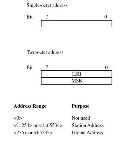
The Common Address (CA) field is either one or two octets (1–2 bytes) long, depending on the system configuration.
The choice of length is fixed on a per-system basis — all stations within the same network must use the same addressing length.
Purpose of the Common Address
The CA uniquely identifies the source or destination of the data. It allows the controlling station (master) to associate every ASDU with a specific remote terminal unit (RTU) or intelligent electronic device (IED).
In large substations or distributed systems, the CA may be divided into station + sector components, where each sector represents a logical sub-unit such as a bay, transformer, or feeder.
Address Range and Special Values
| Value | Meaning |
|---|---|
| 0x0000 (0) | Not used — reserved and should not appear in communication. |
| 1 – 0xFE (254) or 1 – 0xFFFE(65534) | Normal station addresses used for individual RTUs / IEDs. |
| 0x00FF(255) or 0xFFFF(65534) | Global address — interpreted by all stations. Used only for special broadcast functions. |
Note:
The global address (highest possible value) is reserved for a limited number of ASDU types, such as time synchronization, system interrogation, or broadcast activation.
Its use ensures that the same operation is initiated simultaneously across all devices in the system.
Information Object Address (IOA)
The Information Object Address (IOA) is one of the most important fields in an IEC 60870-5-104 ASDU. It uniquely identifies which data point or process variable within a specific station the ASDU refers to.
In essence, while the Common Address of ASDU (CA) identifies which station the data belongs to, the IOA specifies what data inside that station the message relates to.
Purpose of the Information Object Address
The IOA is the first field of every information object in the ASDU. It pinpoints the exact process variable — such as a switch position, analog measurement, or alarm — within the RTU or IED identified by the common address.
This structure ensures that each data point across a large SCADA network is uniquely addressable by combining two fields:
Unique Data Point = (Common Address) + (Information Object Address)
IOA Field Length
The Information Object Address can be 1, 2, or 3 octets (bytes) long, depending on system configuration.
However, in practice:
- 1 octet (8 bits) – Used in small systems with fewer than 256 data points per device.
- 2 octets (16 bits) – Most common; allows up to 65,536 unique addresses per station.
- 3 octets (24 bits) – Optional; reserved for systems that use structured addressing, such as hierarchical device layouts or sectorized substations.
⚠️ Although 3-byte addressing is defined in the standard, each station is limited to 65,536 addresses in practical implementations — matching the 2-octet range.
When combined with the Common Address and Cause of Transmission, the IOA forms a clear and logical data model that supports accurate monitoring, control, and event reporting across complex automation networks.
Information Elements and Time Tags
Each information object contains one or more data elements, such as:
- Binary status (ON/OFF)
- Analog measurement (float or scaled)
- Counter or integrated total
- Command or set-point value
Some ASDUs include timestamps — either CP24Time2a (3 bytes, minutes + milliseconds) or CP56Time2a (7 bytes, full date and time).
These allow the master to reconstruct the exact event sequence across the entire SCADA network.
For detailed explanation of timestamp formats, see: IEC 104 Time Synchronization (CP56Time2a)
Conclusion
The ASDU is the beating heart of IEC 60870-5-104 — a compact yet powerful data unit that standardizes how measurements, commands, and events are exchanged in modern SCADA systems.
By understanding each field — from Type ID and COT to IOA and timestamp — engineers can confidently interpret traffic, diagnose communication issues, and ensure reliable automation.
Whether you’re building, maintaining, or securing a control network, mastering the ASDU structure is the first step toward mastering IEC 104 communication itself.