
IEC 61850 is the modern communication standard used in power utility automation systems. It defines how intelligent electronic devices (IEDs) communicate inside substations and across modern electrical networks. One of the most important technologies inside this standard is MMS (Manufacturing Message Specification). MMS is used for supervisory communication, real-time monitoring, remote control, reporting, configuration, file exchange, and system engineering.
This article provides a full and understandable explanation of MMS in the context of IEC 61850, covering object mapping, communication behavior, engineering practices, and real-world applications. It has been written to be easy to understand and accurate for engineers, students, and professionals in the power industry.
Table of Contents
What MMS Is and Why IEC 61850 Needs It
IEC 61850 is built around the idea that every device in a substation should exchange data using standardized structures. It defines logical nodes, data objects, attributes, datasets, control blocks, and many other elements. These definitions describe what information exists and how it should be used. However, by themselves, these objects are abstract—they have no physical format and cannot be sent over a network.
This is exactly what MMS solves.
MMS (Manufacturing Message Specification) is a communication protocol originally designed for power utility automation. It provides a flexible way to read, write, and exchange structured data over Ethernet. In IEC 61850, MMS acts as the transport method that carries the abstract object model across TCP/IP networks. Without MMS, IEC 61850 devices would not have a common communication language.
In simple terms:
- IEC 61850 defines what information looks like
- MMS defines how this information travels over the network
IEC 61850 MMS is the communication backbone for most non-time-critical functions in IEC 61850, including SCADA integration, monitoring, file transfer, and control.
MMS in the Client–Server Architecture
IEC 61850 MMS operates using a client–server model. This model is straightforward:
- The server is an IED, such as a protection relay, bay controller, transformer controller, or merging unit.
- The client is typically a SCADA system, gateway, automation controller, or engineering tool.
The client always initiates communication. The server only responds or sends reports that have been configured by the client.
In a typical substation setup:
- SCADA enables a Report Control Block (RCB) → The IED automatically sends current, voltage, status, and alarms using MMS Reports when data changes, quality changes, or when the cyclic (integrity) period expires.
- SCADA sends a breaker command → The IED verifies the command and executes it using the MMS Select-Before-Operate or Operate service.
- The relay detects a protection trip or alarm → The relay immediately sends an MMS report to SCADA with the event, timestamp, and quality information.
This makes IEC 61850 MMS suitable for high-level communication, while protection-grade messaging uses GOOSE and Sampled Values.
The IEC 61850 Object Model and How MMS Maps It
One of the most advanced features of IEC 61850 is its unified object model. The model uses several layers:

Logical Devices
A Logical Device groups related functions, such as protection or metering.
Logical Nodes
Logical Nodes describe specific functions, like:
- XCBR – circuit breaker
- MMXU – electrical measurements
- PTRC – protection trip conditioning
- TCTR – current transformer models
Data Objects
Each Logical Node contains Data Objects, such as:
- Pos – breaker position
- A – current measurements
- PhV – phase voltage
Data Attributes
These are the individual values, such as:
- stVal – status value
- mag.f – magnitude (float)
- q – quality
- t – timestamp
IEC 61850 MMS translates all of these layers into something the network can send and receive.
Logical Devices → MMS Domains
In IEC 61850, every Logical Device in an IED is mapped to a MMS Domain.
A Domain is like a container inside the MMS server that holds all Logical Nodes that belong to that Logical Device.
Each Logical Device therefore becomes its own MMS “area” for organizing data.
Logical Nodes → MMS NamedVariables (Structured Data)
Each Logical Node is represented inside MMS as one MMS NamedVariable.
This NamedVariable contains a hierarchical structure of components that represent all Data Objects and Data Attributes of that Logical Node.
For example, in MMS the structure may appear as:
MMXU1$MX$A$phsA$instMag$f
Each “$” marks the next level in the hierarchy.
Data Objects & Data Attributes → MMS NamedVariable Components
Inside the MMS NamedVariable of a Logical Node, every Data Object and Data Attribute becomes a NamedComponent in the hierarchy.
Examples:
XCBR1$ST$Pos→ the Pos Data ObjectXCBR1$ST$Pos$stVal→ the stVal Data AttributeMMXU1$MX$A$phsB$mag$f→ the float magnitude of phase B current
Nothing is hidden or vendor-proprietary—IEC 61850 forces a fully open and standardized structure.
All measurable, status, and control values appear as MMS-accessible components.
DataSets → MMS NamedVariableLists
A DataSet is a list of data references (FCD or FCDA) that an IED groups together for reporting, logging, or batch reading.
A DataSet may include members from:
- the same Logical Node
- different Logical Nodes
- different Data Objects
- different functional constraints (MX, ST, CO, etc.)
IEC 61850-8-1 maps each DataSet directly to a MMS NamedVariableList, and each member is mapped to a listOfVariable entry.
Report Control Blocks → MMS Reports
Reporting is one of the core features of IEC 61850, and it is the main way IEDs deliver real-time information to SCADA systems.
A Report Control Block (RCB) defines what data is reported, when it is reported, and how the report behaves.
When a Report Control Block is enabled by the client, the IED automatically sends MMS InformationReport messages under specific conditions defined in the RCB.
Reports are sent automatically when:
- a data value changes (data change – dchg)
- a quality state changes (quality change – qchg)
- a protection function starts or trips
- an alarm condition becomes active or cleared
- a measurement crosses a configured threshold
- the cyclic integrity timer expires (periodic report)
These rules come directly from the RCB settings—SCADA does not need to poll for updates.
Each report includes:
- the updated DataSet members
- the timestamp of each new value
- the quality bits (validity, source, test, substituted, etc.)
- the reason for inclusion (dchg, qchg, integrity, GI, etc.)
- sequence numbers for tracking event order
- status flags from the RCB (enable, overflow, entryID for buffered reports)
This structured information allows SCADA systems to understand what happened, when it happened, and why the value was included.
Why reports matter
Reports eliminate the need for continuous polling. Instead of SCADA asking for values repeatedly, the IED pushes updates only when the RCB determines they are required.
This approach:
- reduces network traffic
- increases system speed
- ensures events are captured in the correct order
- improves reliability (especially with Buffered Reports)
- guarantees no loss of critical events after reconnection
IEC 61850 reporting is one of the main reasons modern substations achieve fast, deterministic, and standardized communication behaviour.
Logs → MMS Journals
IEC 61850 devices can store historical events locally in Logs.
A Log is managed by a Log Control Block (LCB) and its associated DataSet, similar to how reporting uses Report Control Blocks.
Logs record time-stamped entries whenever DataSet members meet the configured trigger conditions (for example, data change, quality change, or events from a protection function).
When mapped to MMS, these Logs appear as MMS Journal Objects.
This allows SCADA or engineering tools to access stored event history even after communication interruptions.
SCADA or engineering tools can retrieve log entries by:
- entry ID (unique identifier of a log record)
- time range (from a start timestamp to an end timestamp)
- sequence number
- first / next journal entry
This makes it possible to replay event sequences, analyze disturbances, and verify protection actions.
Why logs are important
Logs provide:
- reliable local storage of events inside the IED
- the ability to retrieve historical data after network outages
- precise timestamps and quality information
- a standardized method for event replay and system debugging
Logs complement reporting:
Reports deliver live events, while Logs provide the history of those events.
File Handling → MMS File Transfer
IEC 61850 uses the MMS file services to exchange files between an IED and a client such as SCADA, a gateway, or an engineering tool.
These services allow the client to browse, open, read, and manage files stored inside the IED.
IEC 61850 MMS provides a complete set of file transfer operations:
- FileOpen – open a file stored in the IED
- FileRead – read the contents of the file in blocks
- FileClose – close the file after reading is done
- FileDelete – remove a file (if permitted)
- FileDirectory – list files and directories available in the IED
These file services are used mainly for retrieving:
- disturbance records (COMTRADE)
- sequence-of-events files
- device diagnostic logs
- configuration backups
- fault reports
- relay internal data files
When a protection event happens, the IED typically generates a disturbance file.
Using MMS file transfer, the engineer can download this file directly from the SCADA system or from an engineering workstation without needing vendor-specific tools.
Why MMS file transfer matters
- It provides a standardized way to get important analysis files from any vendor’s device.
- It simplifies fault investigation and post-event analysis.
- It supports cybersecurity rules via IEC 62351 (authentication and access control).
- It enables remote maintenance without local access to the IED.
MMS file handling is therefore a key feature of IEC 61850 systems, supporting efficient diagnostics and disturbance analysis across the substation.
This mapping system is what makes IEC 61850 interoperable across different manufacturers.
MMS Services Used in IEC 61850
IEC 61850 MMS supports many services, but IEC 61850 uses the ones needed for substation automation. Let’s look at the most important ones.
MMS Read Service
The MMS Read service allows a client to directly request the value of specific data items from an IED.
This service can be used to read:
- measurements (such as current, voltage, power)
- breaker and switch statuses
- temperature values
- alarm states
- configuration and settings
- any Data Object or Data Attribute defined in the IEC 61850 model
Although MMS Read can access almost any value, it is not normally used for continuous SCADA polling in IEC 61850 systems. Real-time updates are delivered automatically through Reports.
Instead, MMS Read is typically used for:
- initial value loading when the SCADA system starts up
- engineering and commissioning work
- manual inspection of specific values
- diagnostic checks
- retrieving non-changing or slowly changing data
MMS Read provides flexible access to the full data model, but in normal operation, reporting is the preferred mechanism for delivering live measurements and status updates.
MMS Write Service
The MMS Write service allows a client to send new values to an IED.
This is used when the system needs to modify configuration data or change the behavior of a function inside the device.
Through MMS Write, a client can:
- change protection settings (pickup currents, time delays, characteristics)
- update configuration parameters (logical node settings, communication attributes, limits)
- adjust thresholds for measurements, alarms, or supervision functions
- change operating modes (for example: test mode, auto/manual mode, control authority)
- write control parameters that are required before issuing an actual control command
- modify DataSet or Report settings when supported
Before a Write operation is accepted, the IED performs several checks to ensure the request is valid and secure. These checks may include:
- access rights and role-based permissions
- interlock or safety checks
- verification of control authority (which client is allowed to write)
- validation of the data type and value range
- security requirements defined by IEC 62351
Only after all conditions are met will the IED apply the new value and respond with a confirmation.
MMS Write is a powerful service, but in IEC 61850 systems it is used carefully and under controlled conditions, since it directly affects device behavior and system safety.
Reporting Services
Reporting is one of the most powerful and important features of IEC 61850.
Instead of the client constantly polling the IED for new data, the IED automatically sends MMS InformationReport messages when report conditions are met.
This makes communication faster, lighter, and more dependable.
IEC 61850 defines two types of reporting behavior:
Buffered Reporting (BRCB)
Buffered reports store event entries in an internal buffer inside the IED until the client acknowledges them.
This ensures that no events are lost, even if the network connection is temporarily down.
Buffered reports are typically used for:
- protection trips
- alarms
- important state changes
- events that must be delivered in order and without loss
Buffered RCBs include sequence numbers and entry IDs so the client can reconstruct the exact event timeline.
Unbuffered Reporting (URCB)
Unbuffered reports are sent only when the communication link is active.
If the connection is lost, the IED does not store missed events.
Unbuffered reporting is used for:
- general monitoring
- non-critical status changes
- routine operational data
URCBs provide fast updates without maintaining a stored buffer of events.
Why reporting is so effective
Reports eliminate the need for continuous polling.
Once SCADA enables a Report Control Block:
- the IED automatically sends updates when data changes
- the IED sends periodic “integrity” reports as configured
- the client receives time-stamped and quality-tagged values
- event ordering is preserved using sequence numbers
This approach reduces network traffic, increases responsiveness, and guarantees that important events are captured reliably.
Control Services
IEC 61850 provides a standardized and safe way for SCADA systems to operate primary equipment such as breakers, disconnectors, tap changers, and switches.
Control actions are performed through MMS using a defined set of control models.
These control models ensure that operations are secure, validated, and properly time-stamped.
IEC 61850 supports several control models, including:
- Direct Operate (DO) – a simple operate command sent directly to the IED.
- Select-Before-Operate (SBO) – a two-step process designed to prevent accidental commands.
- Select-Before-Operate with Enhanced Security (SBOw) – includes additional checks such as operator identity, time validity, or interlock confirmation.
- Time-activated Operate – the command is executed at a specific time (scheduled operation).
Among these, SBO/SBOw is the most widely used because it provides a higher level of safety and reduces the risk of unintended switching.
Typical SBO Sequence
A standard SBO control operation follows this sequence:
- SCADA sends a Select request to the control object.
- The IED checks control authority, interlocks, access rights, and whether the object is already selected by another client.
- If accepted, the IED locks the control object for the requesting client for a short period (operational timeout).
- SCADA sends the Operate command within the allowed time window.
- The IED executes the operation, such as opening or closing a breaker.
- The IED sends an Operate response indicating success or a detailed error code.
This two-step process ensures that only a valid and intentional control action is carried out.
Why IEC 61850 Control Is Safer
IEC 61850 control services provide several layers of safety:
- Authority checks (which client is allowed to control)
- Interlock verification (can the device operate safely?)
- Timeouts to prevent stuck selections
- State feedback with clear success or failure responses
- Quality and timestamp attached to control status updates
- Secure profiles when IEC 62351 is used
Compared to older protocols like DNP3 or Modbus (which rely on simple “write” commands), IEC 61850 control is far more robust, structured, and resistant to accidental or unsafe operations.
File Transfer Services
IEC 61850 uses the MMS file service to exchange files between an IED and a client such as SCADA, a gateway, or an engineering workstation. This allows large or detailed files to be retrieved directly from the device without needing vendor-specific software.
MMS provides a complete set of file operations, including:
- FileOpen – open a file stored inside the IED
- FileRead – read the file in blocks until complete
- FileClose – close the file after transfer
- FileDirectory – list the files available in the device
- FileDelete – remove a file (if permitted by the IED)
These services make it possible for engineers to retrieve or manage important files stored by the IED.
Engineers commonly use MMS file transfer to download:
- disturbance records (COMTRADE) generated after faults
- sequence-of-events logs
- IED diagnostic and self-test logs
- configuration backups
- fault reports or internal data files
Because MMS file transfer is standardized, files can be accessed in the same way across devices from different manufacturers.
Why MMS file transfer is important
- It provides a unified, vendor-independent method for accessing IED files
- It supports detailed fault investigation and disturbance analysis
- It simplifies maintenance and remote diagnostics
- It works seamlessly with cybersecurity measures defined in IEC 62351
- It reduces the need for on-site tools or proprietary software
MMS file transfer is therefore a key part of the IEC 61850 ecosystem, enabling reliable and consistent access to critical data for engineering and analysis.
IEC 61850 MMS Communication Stack and Networking
IEC 61850 uses standard Ethernet networks as the foundation for communication between IEDs.
MMS operates on top of the TCP/IP stack, following the communication profiles defined in IEC 61850-8-1.
This layered approach ensures interoperability, performance, and vendor-neutral communication.
The MMS communication stack used in most IEC 61850 systems follows this structure:
- Application Layer → MMS
Handles reading, writing, reporting, control, logs, and file transfer. - Presentation Layer → ASN.1 Encoding Rules
Defines how MMS data structures are encoded (BER/DER). - Session Layer → ACSE (Association Control Service Element)
Establishes and manages the MMS association between client and server. - Transport Layer → ISO-on-TCP (RFC 1006)
Provides reliable delivery of MMS messages on top of TCP. - Network Layer → IP
Routes packets across the local network or larger utility networks. - Data Link Layer → Ethernet (ISO/IEC 8802-3)
Provides frame-based data transmission over copper or fiber. - Physical Layer → Copper or Fiber Optic Cabling
Connects all IEDs, switches, and network devices.
This layered architecture ensures that MMS messages are transported reliably across modern digital substations and utility networks.
Redundancy Mechanisms
IEC 61850 supports high-availability networking through the redundancy protocols defined in IEC 62439-3:
- PRP (Parallel Redundancy Protocol)
Sends identical frames over two independent networks (LAN A and LAN B).
If one network fails, communication continues instantly on the other. - HSR (High-Availability Seamless Redundancy)
A ring-based redundancy protocol where nodes forward frames around the ring.
Provides zero-time recovery for critical protection and control traffic.
These redundancy methods allow:
- zero packet loss
- no switchover delays
- continuous communication during failures
This is essential for protection and control applications in digital substations.
How MMS Compares to GOOSE and Sampled Values
IEC 61850 defines three main communication mechanisms in a digital substation. Each one has a different purpose, different timing requirements, and different protocol behavior.
MMS (Manufacturing Message Specification)
MMS uses a client–server model and runs on TCP/IP over Ethernet.
It is designed for supervisory functions, configuration, engineering tasks, and general monitoring.
MMS is used for:
- SCADA communication
- event and measurement reporting
- device configuration
- control commands (SBO, direct operate)
- file transfer and logs
MMS is “medium speed” because it uses TCP/IP, but it is reliable, structured, and fully object-oriented.
GOOSE (Generic Object Oriented Substation Event)
GOOSE uses publisher–subscriber communication directly on Layer 2 Ethernet, with no TCP/IP overhead.
This allows extremely fast delivery of protection-critical signals.
GOOSE is used for:
- protection trips
- breaker failure signals
- interlocking
- fast status updates
- peer-to-peer messaging between IEDs
Typical GOOSE times are in the 2–4 ms range, making it suitable for protection applications.
Sampled Values (SV)
Sampled Values provide extremely high-speed streaming of analog measurements, replacing traditional copper wiring from CTs and VTs.
SV is used for:
- current samples
- voltage samples
- digital merging unit data
- differential and distance protection applications
SV streams very high frame rates (e.g., 4,800 samples per second at 50 Hz), carrying precise measurement data for protection relays.
How the Three Fit Together in a Digital Substation
Each communication type serves a different level of substation operation:
- MMS → supervisory control, monitoring, settings, reports, files
- GOOSE → high-speed protection signaling and interlocking
- SV → ultra-fast measurement streams from CTs/VTs
All three technologies complement one another:
- MMS provides structured communication for SCADA and engineering
- GOOSE ensures fast, deterministic protection behavior
- SV delivers real-time measurement data for advanced protection logic
Together, they form the complete communication framework required for a modern IEC 61850 digital substation.
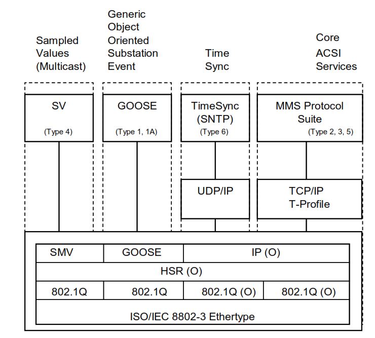
The figure below shows how the main IEC 61850 communication types—Sampled Values (SV), GOOSE, Time Synchronization, and MMS—map to different protocol layers. It illustrates the complete stack from the Ethernet layer up to the application services.
Real-World MMS Applications
IEC 61850 MMS is used throughout a substation, supporting day-to-day operation, supervision, engineering, and analysis.
It plays a major role in almost every interaction between IEDs and SCADA or engineering systems.
Monitoring
IEC 61850 MMS provides the data that SCADA needs to supervise the health and behavior of the substation.
Depending on the reporting configuration, SCADA receives live updates for:
- breaker and switch positions
- phase currents and voltages
- transformer temperatures and oil levels
- battery and charger status
- energy values, power factor, frequency, and more
Most of these values are delivered through automatic MMS reports, not continuous polling.
Event Reporting
When something important happens inside an IED, MMS is used to send real-time event messages to SCADA.
IEDs send instant reports when:
- protection trips occur
- alarms become active or clear
- supervision detects abnormal conditions
- device states change (for example, a breaker opens)
- thresholds are crossed
- quality bits change
Because these reports are timestamped by the IED, SCADA receives accurate event chronology.
Remote Control
MMS supports the entire IEC 61850 control model, allowing operators to remotely control primary equipment safely.
Control functions include:
- opening and closing circuit breakers
- operating disconnectors
- changing tap positions
- switching between modes (auto/manual/test)
- initiating sequences or procedures
These operations use Select-Before-Operate (SBO) or Enhanced SBO, ensuring safe and intentional switching.
Disturbance File Downloads
After a fault or unusual event, the IED typically generates a COMTRADE disturbance file.
MMS file transfer allows engineers to download these files directly from the device, without using vendor-specific tools.
This supports:
- fault analysis
- event reconstruction
- relay setting verification
- protection performance evaluation
MMS file services (FileOpen, FileRead, FileClose, etc.) make this process standardized across all vendors.
Asset Management
Utilities use MMS data to monitor the condition of equipment and plan maintenance.
Examples include:
- monitoring temperature trends
- identifying abnormal operating conditions
- tracking breaker operation counts
- supervising relay self-diagnostics
- checking power quality indicators
This helps detect issues early and extend the life of equipment.
Commissioning and Engineering
During testing and commissioning, engineering tools use MMS extensively.
IEC 61850 MMS enables:
- browsing Logical Devices and Logical Nodes
- reading DataSet contents
- enabling/disabling Report Control Blocks
- checking live values during testing
- verifying that reporting and control functions work correctly
- updating settings and configuration
The standardized data model makes the engineering workflow consistent across different IED brands.
IEC 61850 MMS is involved in nearly every operational, engineering, and diagnostic function in a digital substation.
It forms the backbone of supervisory communication, from live monitoring and control to event reporting and data analysis.
Why IEC 61850 MMS Matters for the Digital Grid
Modern power systems are moving rapidly toward digitalization.
Substations, renewable plants, distribution networks, and control centers are becoming more automated, more data-driven, and more interconnected than ever before.
MMS plays a critical role in enabling this digital transformation.
MMS matters because:
- It carries structured, standardized information.
Every Logical Node, Data Object, and Data Attribute is transmitted in a clear, well-defined format that all vendors understand. - It supports the full IEC 61850 data model.
MMS can represent complex, hierarchical device information without vendor-specific extensions. - It is reliable and field-proven.
MMS runs on top of TCP/IP and uses stable, acknowledged communication for supervisory data. - It strengthens automation.
MMS enables SCADA, gateways, and automation systems to access real-time values, execute control commands, retrieve reports, and manage files in a secure and structured way. - It scales with future system growth.
Whether a utility has a single substation or a nationwide network, MMS can scale to support thousands of IEDs and millions of data points. - It enables multi-vendor interoperability.
The same MMS services work across all manufacturers, helping utilities avoid vendor lock-in.
As smart grids expand, with more renewable generation, distributed energy resources, and advanced protection schemes, MMS remains a central building block.
It provides the communication foundation required for safe, reliable, and interoperable digital substations—today and in the future.
Conclusion
IEC 61850 MMS is one of the key technologies that makes modern digital substations possible. It provides a structured, standardized, and reliable way for SCADA systems, engineering tools, and automation equipment to communicate with IEDs.
MMS gives utilities a unified method to:
- access measurements and status information
- receive real-time event reports with accurate timestamps
- operate breakers and other primary equipment safely
- download disturbance records and diagnostic files
- read and write configuration settings
- browse device data models during engineering and commissioning
Because MMS is based on the IEC 61850 object model, every value inside the IED is represented in a clear, defined, and vendor-independent structure. This brings consistency across substations, manufacturers, and system architectures.
IEC 61850 MMS is not designed to replace high-speed protection messaging—GOOSE and Sampled Values handle that part—but it forms the backbone of supervisory communication, asset management, engineering, and control room operations.
As utilities evolve toward smarter, more automated grids, IEC 61850 MMS will remain a central technology. Its combination of openness, interoperability, scalability, and robustness makes it ideal for the complex and connected power systems of today and the future.
IEC 61850 MMS is more than just a protocol, it is a fundamental building block for safe, reliable, and fully digital power networks.