
IEC 61158-2 defines the physical layer specification for industrial fieldbus communication systems. It establishes the electrical, optical, and timing rules that allow deterministic data transmission between industrial devices.
While IEC 61158-1 defines the architecture of the standard,
IEC 61158-2 defines how bits physically travel across copper and fiber media.
This article explains the IEC 61158-2 physical layer in clear, practical language for automation engineers, PLC programmers, and industrial network designers.
Table of Contents
1. What the Physical Layer Does
The physical layer (Layer 1 of the OSI model) handles:
- Electrical or optical signaling
- Transmission of bits
- Signal timing
- Clock recovery
- Physical connectors and interfaces
It does not interpret data.
It does not understand frames.
It simply ensures that bits move reliably from one device to another.
In industrial systems, reliability and timing precision are critical. That is why IEC 61158-2 is so detailed.
2. Media Types Defined in IEC 61158-2
IEC 61158-2 supports multiple transmission media to fit different industrial environments.
Twisted-Pair Cable
- Most common in industrial automation
- Uses differential signaling
- Resistant to electromagnetic noise
- Cost-effective and easy to install
Widely used in fieldbus networks on factory floors.
Coaxial Cable
- Strong shielding
- Defined voltage-mode signaling for specific implementations
- Suitable for certain legacy or specialized systems
Optical Fiber
- Immune to electromagnetic interference
- Provides electrical isolation
- Suitable for long distances
- Ideal for high-noise industrial environments
Different fieldbus Types may use different media, but IEC 61158-2 defines how each medium must behave.
3. Physical Layer Services
The physical layer provides services to the data-link layer, including:
- Transmission of user data
- Reception of user data
- Carrier detection
- Frame detection
- Status indication
These services allow the higher layer to know when data is successfully transmitted or received.
The physical layer moves bits.
The data-link layer interprets frames.
4. IEC 61158-2 Physical Layer Architecture Diagram
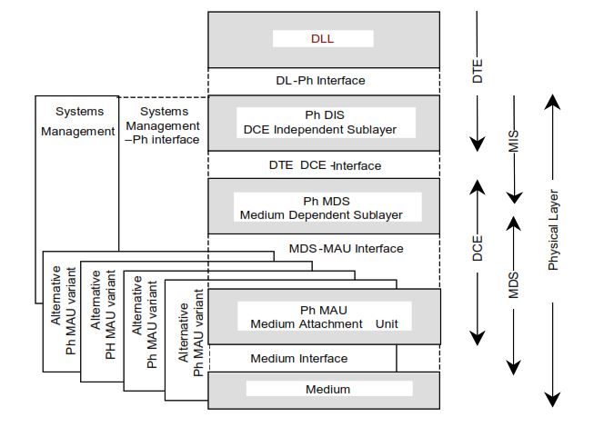
This diagram illustrates the internal structure of the IEC 61158 physical layer.
From top to bottom:
- DLL (Data Link Layer)
Communicates with the physical layer through the DL–Ph interface. - Ph DIS (DCE Independent Sublayer)
Provides services independent of the physical medium. - Ph MDS (Medium Dependent Sublayer)
Adapts signaling to the specific transmission medium. - Ph MAU (Medium Attachment Unit)
Handles the electrical or optical transmission. - Medium
The actual transmission medium such as twisted pair, coaxial cable, or optical fiber.
On the left side, systems management interfaces allow configuration and monitoring.
On the right side, the diagram separates DTE, DCE, MDS, and the physical layer boundary.
5. Clock Accuracy and Data Recovery
Industrial control requires deterministic communication.
That means:
- Frames must arrive within precise time windows
- Jitter must be controlled
- Clock drift must be limited
IEC 61158-2 defines clock accuracy and data recovery rules to maintain stable timing.
Without precise clock control:
- Cyclic updates fail
- Control loops become unstable
- Real-time guarantees disappear
Timing begins at the physical layer.
6. Encoding and Decoding Rules
To transmit data correctly, bits must be encoded into electrical or optical signals.
IEC 61158-2 defines:
- Bit encoding methods
- Polarity detection
- Synchronization sequences
- Frame delimiters
These rules ensure that the receiving device can correctly interpret incoming signals even in noisy industrial environments.
Encoding methods may differ by Type, but the standard framework remains consistent.
7. DTE–DCE Interface
IEC 61158-2 defines the interface between:
- DTE (Data Terminal Equipment) – the protocol logic or controller
- DCE (Data Communication Equipment) – the physical transmission hardware
This separation allows:
- Modular hardware design
- Clear conformance testing
- Independent development of higher-layer software
In simple terms:
The DTE processes the protocol.
The DCE transmits the signal.
8. Medium Dependent Sublayer (MDS)
Within the physical layer, IEC 61158-2 defines the Medium Dependent Sublayer (MDS).
The MDS handles:
- Signal encoding
- Frame delimiters
- Synchronization
- Preamble handling
- Inter-frame timing
The MDS adapts logical protocol frames to the actual physical medium (copper or fiber).
It ensures that the physical transmission matches the data-link layer requirements.
9. Medium Attachment Unit (MAU)
The MAU connects the device to the physical medium.
It handles:
- Signal driving
- Signal reception
- Electrical compliance
- Protection mechanisms
IEC 61158-2 defines the interface between the MDS and MAU to ensure compatibility and reliability.
The MAU is where hardware engineering meets the communication standard.
10. Signaling Methods
Depending on the fieldbus Type, IEC 61158-2 may define:
- Voltage-mode signaling
- Differential signaling
- Optical signaling
Differential signaling is common in industrial systems because it:
- Reduces noise sensitivity
- Improves signal integrity
- Provides better EMI resistance
Industrial environments are electrically noisy.
The signaling method must be robust.
11. Frame Delimiters: SOF and EOF
The physical layer defines:
- Start-of-Frame (SOF) markers
- End-of-Frame (EOF) markers
These markers help receivers detect frame boundaries.
Clear frame detection is essential for cyclic deterministic communication.
12. Idle States and Inter-Frame Gaps
IEC 61158-2 specifies:
- Idle signal states
- Post-transmission gaps
- Inter-frame timing requirements
These rules:
- Prevent collisions
- Maintain cycle timing
- Support synchronization between devices
Determinism depends on consistent timing — even between frames.
13. Physical Layer and Determinism
Deterministic communication requires:
- Stable voltage levels
- Controlled signal transitions
- Accurate clock synchronization
- Defined timing windows
The physical layer provides the electrical foundation that makes deterministic fieldbus communication possible.
If the physical layer is unstable:
- Frames may be corrupted
- Timing cycles may drift
- Control systems may fail
Determinism begins at Layer 1.
14. Practical Engineering Considerations
When implementing IEC 61158-2 in real systems:
Cable Selection
Use the correct impedance and shielding.
Proper Termination
Incorrect termination causes reflections and signal distortion.
Grounding Strategy
Improper grounding can introduce noise and communication faults.
Noise Protection
Use isolation and shielding in high-EMI environments.
Clock Stability
Ensure oscillators meet accuracy requirements.
Small physical mistakes can cause large communication failures.
15. Common Physical Layer Problems
Typical issues include:
- Incorrect cable impedance
- Missing termination resistors
- Excessive cable length
- Electromagnetic interference
- Poor shielding
- Clock drift
Understanding IEC 61158-2 helps engineers diagnose these issues quickly.
16. How IEC 61158-2 Supports Multiple Fieldbus Types
Each IEC 61158 “Type” may use:
- Different signaling methods
- Different encoding rules
- Different media
IEC 61158-2 provides the structured framework that allows these variations while maintaining standardization.
This ensures:
- Clear documentation
- Consistent layer separation
- Interoperability within defined Types
17. Why This Matters for SCADA Systems
Even if you work primarily at the SCADA or application level, physical layer problems often cause system-wide failures.
Understanding IEC 61158-2 helps you:
- Diagnose communication faults
- Evaluate hardware specifications
- Design reliable installations
- Prevent downtime
When communication fails, the problem often starts at the physical layer.
Final Summary
IEC 61158-2 defines the physical layer of industrial fieldbus systems.
It specifies:
- Transmission media (twisted pair, coaxial, optical)
- Signaling methods
- Encoding and decoding rules
- Clock accuracy requirements
- DTE–DCE interfaces
- Medium Dependent Sublayer (MDS)
- Medium Attachment Unit (MAU)
- Frame delimiters and timing rules
It provides the electrical and timing foundation required for deterministic industrial communication.
Without a stable physical layer, real-time industrial control is impossible.
IEC 61158-2 ensures that fieldbus systems are robust, predictable, and interoperable at the hardware level.
Isso é muito bom