IEC-60870-5-101 (IEC-101) and IEC-60870-5-104 (IEC-104) are two of the most important communication protocols used in electrical power systems, especially in substations and national SCADA systems. Both belong to the IEC-60870-5 family, which defines how remote telecontrol data is exchanged for monitoring, supervision, and automation. Even though the two protocols share the same information structure (ASDUs), they behave very differently at the physical, link, and transport layers.
IEC-101 was created when communication channels were slow, unreliable, and mostly serial. IEC-104 came later when utility networks started moving to Ethernet, IP, optical fiber, and wide-area networks. Understanding the differences between these two protocols is essential for engineers who design substations, communication links, or gateways that convert IEC-101 to IEC-104.
This article gives a full technical breakdown of both protocols, explains how each layer works, shows the real differences, and describes exactly how conversion between them happens inside gateway devices.
Table of Contents
Background and Purpose of Each Protocol
IEC-101 was finalized in the early 1990s to support telecontrol over serial communication lines. Utilities at that time used copper cables, power-line carriers, serial radio links, dial-up modems, and low-bandwidth leased lines. Because these links were slow and noisy, the protocol had to be extremely careful with error detection, link supervision, and timing.
IEC-104 was introduced later as a “network access companion standard” for IEC-101. Instead of serial channels, it uses TCP/IP networks. It encapsulates IEC-101 ASDUs into network frames and removes the need for the rigid serial-link mechanisms that IEC-101 uses. In short, IEC-104 keeps the data model of IEC-101 but replaces the transport mechanism.
While IEC-101 is still used in many remote or old substations, IEC-104 is now the dominant protocol in modern energy management systems and national control centers.
Communication Architecture Overview
Even though both protocols ultimately carry the same application data, the layers under that are completely different.
IEC-101 Architecture
IEC-101 follows a strict three-layer model:
- Physical layer → serial communication (V.24, V.28, X.24, X.27, RS-232, RS-485).
- Data Link layer → FT 1.2 frame formats, balanced/unbalanced modes.
- Application layer → ASDU structures, information objects.
IEC-104 Architecture
IEC-104 shifts completely to the TCP/IP stack:
- Physical layer → Ethernet.
- Data Link layer → Ethernet frames.
- Network layer → IP.
- Transport layer → TCP (port 2404).
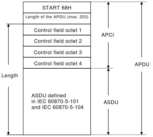
- Application layer → APCI + ASDU.
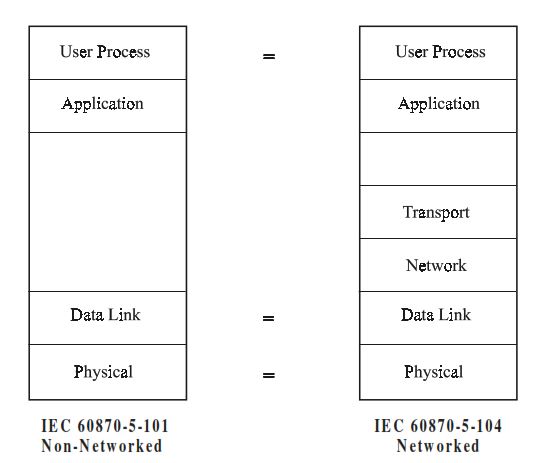
The difference in architecture is the foundation of all technical differences between the two protocols.
Physical Layer Technical Differences
IEC-101 Physical Layer
IEC-101 uses serial communication. The standard supports:
- Asynchronous modes using V.24/V.28.
- Synchronous digital communication using X.24/X.27.
- Channels with bandwidth as low as 300 bps.
- Long-distance copper lines where noise and attenuation are common.
- Multipoint circuits where many RTUs share one line.
Because of this environment, the protocol must compensate for noise, collisions, slow delivery, and long delays.
IEC-104 Physical Layer
IEC-104 assumes a stable IP network. Anything that supports IP—Ethernet, fiber optics, radio IP links, MPLS, VPN, satellite IP—will work. Because of the high available bandwidth, IEC-104 does not need to compress data, limit frame size, or use low-level retries; TCP handles all of that.
Data Link Layer: Deep Technical Comparison
The link layer is where the largest differences exist. This layer defines how data units are packaged, checked, acknowledged, and synchronized.
IEC-101 Data Link Layer (Serial-based, IEC-60870-5-2)
IEC-101’s data link layer is highly structured because it must overcome serial line limitations. Important characteristics include:
Balanced vs. Unbalanced Mode
- Unbalanced mode: the master (controlling station) initiates all communication. The slave (outstation/RTU) only responds.
This is ideal for multipoint or party-line circuits. - Balanced mode: both sides may initiate messages.
This is used mostly in point-to-point links.
Frame Formats (FT 1.2)
IEC-101 defines two major frame types:
- Fixed Frame (10h) – used for simple commands or acknowledgments.
- Variable Frame (68h) – carries ASDUs.
- Single Control Character (0xE5) – 1-byte quick acknowledgment.
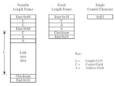
Error Handling and Checksum
Every frame has a checksum (simple SUM modulo 256). Although this method is old, it was chosen for speed on slow channels.
Line Control
Single-byte acknowledgments (0xE5) efficiently manage half-duplex and multipoint lines.
IEC-104 Data Link Layer (APCI on TCP/IP)
IEC-104 does not use the IEC-101 data link layer. Instead, it replaces it with the APCI (Application Protocol Control Information) header. TCP/IP already handles:
- Error detection
- Retransmissions
- Ordering
- Flow control
So IEC-104 only needs a light mechanism to synchronize application data.
The APCI defines three frame types:
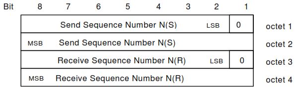
I-Frames (Information Frames)
Carry ASDUs.
Include:
- send sequence number,
- receive sequence number.
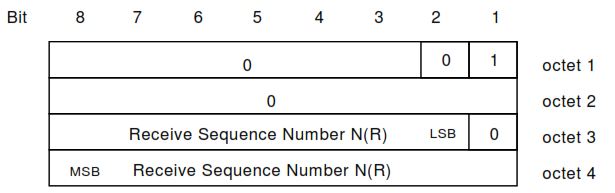
S-Frames (Supervisory Frames)
Used to acknowledge received I-frames when no new data is sent. They help control flow when large volumes of data are coming.
U-Frames (Control Frames)
Control the session:
- STARTDT act/con → start data transfer
- STOPDT act/con → stop data transfer
- TESTFR act/con → test link health
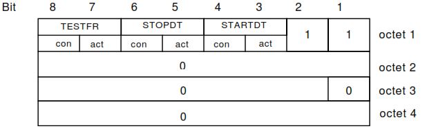
These mechanisms allow IEC-104 to operate like a reliable session, something IEC-101 cannot do.
Transport Layer Differences
IEC-101
No transport layer. Serial lines deliver raw frames.
IEC-104
Uses TCP, which provides:
- guaranteed delivery,
- reordering of packets,
- retransmissions,
- congestion avoidance,
- segmentation,
- flow control,
- session establishment.
By using TCP, IEC-104 gains enormous stability and scalability benefits.
Application Layer: ASDU-Level Technical Analysis
Even though the lower layers are different, IEC-101 and IEC-104 share the same ASDU definition. The ASDU contains:
- Type Identification (TI)
- Variable Structure Qualifier (VSQ)
- Cause of Transmission (COT)
- Common Address of ASDU (CA)
- Information Object Address (IOA)
- Information elements (data)
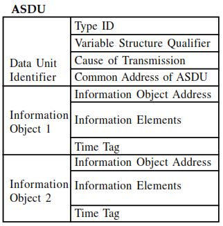
This uniformity is the reason conversion between the two protocols is possible.
Addressing Scheme Differences
IEC-101 uses two levels of addressing:
- Link Address (required for serial link management)
- Common Address (ASDU address)
- Information Object Address (IOA)
Because serial lines may support multiple RTUs per channel, the link address is essential.
IEC-104 removes link addressing. TCP/IP handles routing, so only:
- Common Address
- IOA
are required. This simplifies configuration.
Timing Behavior and Supervision
IEC-104 uses its own timing system that is different from IEC-101 because it operates over TCP/IP networks instead of serial lines. IEC-104 defines three main timers: t1, t2, and t3. The t1 timer specifies how long a sender waits for an acknowledgment for I-frames. The t2 timer determines how long the receiver may wait before sending an acknowledgment when it has received data but has not transmitted anything back. The t3 timer specifies how long the connection may remain idle; when it expires, the sender issues a TESTFR act frame to verify communication health.
In addition to these timers, IEC-104 defines parameters such as k, the maximum number of outstanding unacknowledged I-frames, and w, the maximum number of I-frames the receiver can accept before sending an acknowledgment. These timing and flow-control mechanisms ensure reliable data transfer, but they rely on TCP rather than the strict physical-layer timing used in IEC-101.
Therefore, IEC-104 does not use IEC-101 timers such as T0 (timeout for primary station), T1 (ack wait), T2 (response wait), T3 (test frame interval), and Tr (reaction time) are strictly defined. Because slow lines can be unstable, the link layer must detect lost frames, repeated frames, and line disturbances quickly.
Time Synchronization Differences
IEC-101 time sync is handled through a command sent over the serial link. Because serial communication can have unpredictable delays, IEC-101 relies heavily on the clock in the RTU and uses time tags like CP24Time2a (minutes + milliseconds) or CP56Time2a (full timestamp). The master must compensate for transmission delay and repeat sync regularly, especially on slow or noisy lines.
IEC-104 time sync is more accurate because it runs over TCP/IP, which provides faster and more predictable transmission. IEC-104 normally uses CP56Time2a for full timestamps, and the master can synchronize the RTU with much lower delay. The protocol also supports frequent and reliable time-sync commands since network latency is very small. IEC-104 systems often integrate with NTP/PTP for high-precision timing across the entire network.
Performance Differences
The two protocols differ drastically in data capacity.
IEC-101 Performance
- Very low speed (usually < 9600 bps).
- Low frame size.
- High overhead for link supervision.
- Poor support for high event rates.
- File transfer is slow and fragile.
IEC-104 Performance
- Network speeds of 100 Mbps or more are common.
- Supports many RTUs or remote substations.
- Can handle thousands of messages per second.
- Suitable for wide-area automation and high-speed event reporting.
- File transfer is fast and reliable.
In modern utility systems where event logs, disturbance files, and oscillography must be transmitted, IEC-104 is far more capable.
Redundancy and Availability
IEC-101 does not include any formal redundancy mechanism. Systems typically achieve redundancy by:
- using redundant serial lines,
- deploying redundant RTUs,
- or duplicating entire communication paths.
IEC-104 directly incorporates redundancy into the standard. The 2006 edition defines:
- dual TCP connection support,
- synchronization mechanisms,
- state transition diagrams for redundant link management,
- automatic failover between active and standby connections.
Redundancy is essential in modern national grid SCADA where high availability is mandatory.
Security Differences
IEC-101 has no built-in security mechanisms. Serial lines are often isolated, but if they are tunneled through IP networks, they become vulnerable.
IEC-104 itself also does not mandate encryption, but because it uses TCP/IP, it can be secured with:
- VPN and IPSec,
- TLS tunnels,
- firewalls,
- IEC-62351 (recommended security standard).
Many utilities now apply strong network segmentation to isolate IEC-104 communications from corporate networks.
Detailed Explanation of IEC-101 to IEC-104 Conversion
Conversion between IEC-101 and IEC-104 is required because many field RTUs and legacy devices still communicate using IEC-101 serial, while modern SCADA and control centers use IEC-104 over TCP/IP.
A protocol gateway is therefore placed between them. The application-layer ASDU is identical in both standards, but the transport, link, and session mechanisms are completely different.
Because of this, the gateway must behave like an IEC-101 master on the serial side and an IEC-104 slave/server on the TCP/IP side.
How Conversion Works Internally
1. On the IEC-101 Side (Serial Communication)
The gateway acts as an IEC-101 master. It performs:
- Opening and managing the serial communication line
- Synchronizing the IEC-101 link layer with the RTU
- Operating in balanced or unbalanced mode depending on the RTU
- Sending and receiving IEC-101 acknowledgments (E5h)
- Applying IEC-101 link-layer timers such as T0, Tr, T1…
- Parsing FT 1.2 frame formats (fixed or variable)
- Validating checksum and link address
- Extracting the ASDU from inside the IEC-101 frame
At this point the gateway has a clean ASDU exactly as defined in IEC-101.
2. On the IEC-104 Side (Ethernet/TCP Communication)
The gateway acts as an IEC-104 server. It performs:
- Establishing the TCP connection with the IEC-104 control center
- Starting data transfer using the STARTDT act → STARTDT con handshake
- Creating an IEC-104 APDU (APCI + ASDU) for each message received from IEC-101
- Assigning IEC-104 send and receive sequence numbers
- Handling IEC-104 I-frames, S-frames, and U-frames
- Managing IEC-104 timers t1, t2, and t3 to keep the session healthy
The gateway simply repackages the ASDU from a serial IEC-101 frame into an IEC-104 TCP frame. All important ASDU fields—Type ID, COT, CA, IOA, data, quality, timestamps—remain identical. Only the transport layer and link/session handling are changed, which makes IEC-101 devices compatible with IEC-104 SCADA systems.
Conclusion
IEC-101 and IEC-104 share the same information structure but use completely different communication mechanisms. IEC-101 is optimized for serial networks with strict link-layer behavior, fragile timing, and low speeds. IEC-104 is optimized for high-speed IP networks with reliable sessions, redundancy, scalability, and network-level security.
Conversion between the two is possible because the ASDU structure is identical. A gateway must handle the complexity of serial line supervision on one side and TCP session management on the other. As utilities upgrade to IP-based systems, IEC-104 has become the dominant standard, but IEC-101 will continue to exist in remote or legacy environments for many years.
Thank you, and may God be kind to you, Mr Zakaria.