Reliable communication in IEC 60870-5-104 depends heavily on properly tuned timeout parameters.
The standard defines several timing constants — t0, t1, t2, and t3 — which control connection setup, data acknowledgment, and link supervision between the controlling station (master) and the controlled station (slave/RTU).
Misconfigured timeouts can cause link resets, delayed data updates, or even total communication failure.
Table of Contents
What Are Timeout Parameters in IEC 104?
Timeouts are timing thresholds that determine how long a device waits for a response or activity before taking corrective action.
In IEC 104 (built on TCP/IP), these values ensure that both sides maintain synchronized communication sessions.
IEC 104 inherits these concepts from IEC 60870-5-101, adapting them for network-based communication instead of serial links.
Overview of the Four Timeout Parameters
| Parameter | Meaning | Typical Range (s) | Default Example |
|---|---|---|---|
| t0 | Connection establishment timeout — time allowed for TCP + IEC 104 link setup. | 10–30 | 30 s |
| t1 | Acknowledgment timeout — time to wait for acknowledgment of an I-format APDU. | 10–60 | 15 s |
| t2 | Acknowledgment delay — time before sending an acknowledgment when no I-format APDUs are received. | 1–10 | 5 s |
| t3 | Idle supervision timeout — maximum idle period before sending a TEST FR ACT to confirm link activity. | 20–300 | 25 s |
Detailed Explanation of Each Timeout
1. t0 – Connection Establishment Timeout
- Starts when a station attempts to open the TCP session.
- If no response is received before t0 expires, the connection is considered failed.
- Typical cause of timeout: network issues, port blocking, or unresponsive RTU.
Tip:
- Use longer t0 for high-latency or VPN links (e.g., 30–60 s).
- For LAN or fiber connections, 10 s is sufficient.
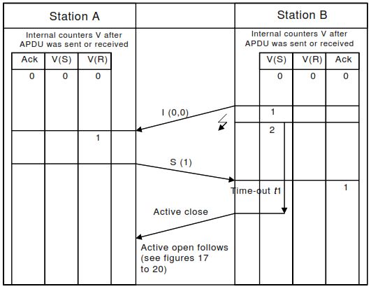
2. t1 – I-Format Acknowledgment Timeout
- Applies after sending an I-format APDU (data frame).
- If acknowledgment (S-format or I-format) is not received within t1, the sender closes and reopens the connection.
- This is the most critical timeout affecting communication reliability.
Example:
- If t1 = 15 s and an RTU is temporarily busy, the master may prematurely disconnect.
- Increasing t1 to 30 s often resolves “frequent reconnect” issues.
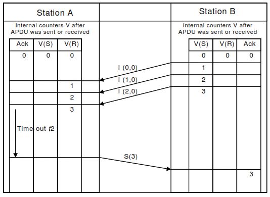
3. t2 – Acknowledgment Delay Timer
- When no new data arrives, t2 defines the delay before the receiver sends a standalone S-format acknowledgment.
- Prevents unnecessary acknowledgments when data flow is continuous.
- If t2 expires without new I-frames, the receiver sends an acknowledgment to keep the session active by an S format APDU.
Tuning:
- Too short → extra network traffic.
- Too long → possible t1 expiry on the sender.
Keep t2 < t1 / 2 as a rule of thumb.
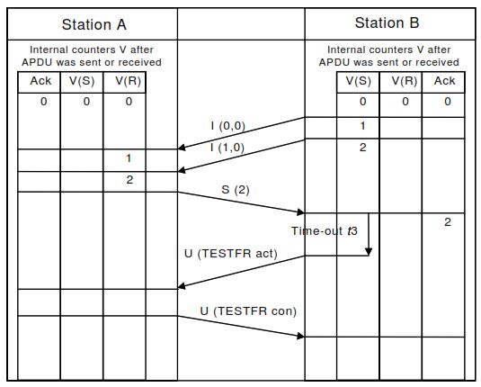
4. t3 – Idle Supervision Timer
- Supervises the link during idle periods.
- When t3 expires, the controlling station sends a TEST FR ACT (U-frame) to confirm the session is alive.
- The controlled station must respond with TEST FR CON.
Use:
- Maintains heartbeat in low-traffic networks and detects silent disconnections.
- Common settings: 20 – 120 s.
How These Timers Interact
- t1 > t2 > network delay
- t3 ≫ t1 (usually 2–4× t1)
- t0 > t1 + t2 (for establishing before watchdogs fire)
Proper proportioning prevents unnecessary resets and ensures smooth TCP keep-alive behavior.
Example Configuration
| Scenario | Network Type | t0 | t1 | t2 | t3 |
|---|---|---|---|---|---|
| Control Center ↔ RTU via LAN | Fiber or local Ethernet | 10 s | 15 s | 5 s | 25 s |
| Regional SCADA ↔ Remote RTU (4G/VPN) | Public Internet | 30 s | 45 s | 10 s | 120 s |
| Power Utility WAN (MPLS) | Managed network | 20 s | 30 s | 10 s | 60 s |
Testing and Optimization Steps
- Monitor connection logs for frequent resets — often caused by t1 timeouts.
- Capture traffic in Wireshark to check S-frame acknowledgments.
- Filter:
iec104.apci.type == 1(S-format)
- Filter:
- Adjust t1/t2 gradually to balance reliability and latency.
- Simulate link loss to verify that t3 triggers TEST FR ACT properly.
- Document all timeout changes for system acceptance testing.
Common Timeout-Related Issues
| Symptom | Probable Cause | Fix |
|---|---|---|
| Frequent reconnects | t1 too short | Increase t1 → 30 s |
| Delayed data updates | t2 too long | Reduce t2 → 1–3 s |
| “Link idle” alarms | t3 too short | Extend t3 → 60 s |
| Connection failure | t0 expired | Check firewall or port 2404 |
| Unacknowledged frames | Mismatch between t1 and t2 | Keep t2 < t1 / 2 |
Best-Practice Recommendations
- Begin with default manufacturer values (t0 = 30, t1 = 15, t2 = 10, t3 = 25).
- Tune gradually while monitoring logs.
- Ensure time synchronization (CP56Time2a) is active — some devices timestamp timeout events.
- Avoid setting t1 shorter than actual network round-trip time.
- Test both normal and failure modes under load.
Next Step: Decode & Test Your IEC 104 Frames
To verify your timeout tuning, analyze real frame sequences with CP56Time2a timestamps using the free IEC 60870-5-104 Frame Decoder.