The IEC 60870-5-101 protocol (commonly known as IEC 101) is a serial telecontrol standard widely used in SCADA, power automation, and industrial control systems.
It defines how data is formatted and transmitted between a controlling station (master) and controlled stations, such as RTUs or dedicated substation operation and data-handling devices.
Each message on the line is called a frame, and understanding the frame format is essential for proper decoding, testing, and troubleshooting.
IEC 101 communication protocol relies on two key frame structures — the Fixed-Length Frame and the Variable-Length Frame — both derived from the IEC 60870-5-1 and IEC 60870-5-2 link layer definitions.
Table of Contents
The Two Types of IEC 101 Protocol Frames
| Frame Type | Use Case | Frame Length | Typical Purpose |
|---|---|---|---|
| Fixed-Length Frame | Link management and simple commands | 5 bytes | Acknowledgments, control commands |
| Variable-Length Frame | Application data exchange (ASDUs) | Variable (up to 255 bytes) | Measurement, events, data transfer |
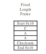
Fixed-Length Frame Format (5 Bytes)
Fixed-length frames are the simplest IEC 101 frame type.
They are used mainly for link control commands, acknowledgments, and test messages between stations.
| Field | Size | Example | Description |
|---|---|---|---|
| Start | 1 byte | 0x10 | Start character (fixed) |
| Control Field | 1 byte | 0x49 | Contains function code and direction bits |
| Link Address (A) | 1 byte | 0x01 | Address of the target station |
| Checksum (CS) | 1 byte | Calculated | Sum of previous bytes modulo 256 |
| End | 1 byte | 0x16 | Frame terminator |
Fixed-length frames (FT1.1) are typically used for polling, link tests, and resets — not for carrying telemetry data.
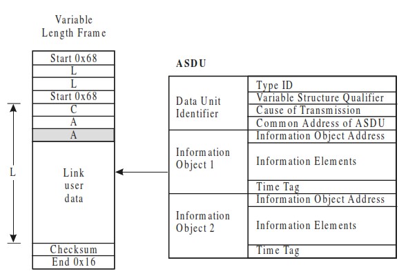
Variable-Length Frame Format (FT1.2)
The variable-length frame is used to transmit ASDUs (Application Service Data Units) — the actual information payloads containing measurements, events, or control signals.
| Field | Size | Example | Description |
|---|---|---|---|
| Start | 1 byte | 0x68 | Start character |
| Length (L) | 1 byte | 0x0E | Number of bytes between 2nd start and end (0x16) |
| Length Repeat (L) | 1 byte | 0x0E | Repetition of length for validation |
| Start (Repeat) | 1 byte | 0x68 | Confirms start of frame |
| Control Field | 1 byte | 0x08 | Direction, function code |
| Link Address (A) | 1–2 bytes | 0x01 00 | Address of destination RTU or station |
| ASDU | Variable | e.g., 06 00 01 00 00 00 14 00 00 | Contains data, Cause of Transmission (COT), and information objects |
| Checksum (CS) | 1 byte | Calculated | Verifies data integrity |
| End | 1 byte | 0x16 | Frame terminator |
Control Field in IEC 60870-5-101
The Control Field is a key element of every IEC 60870-5-101 frame.
It defines the direction, purpose, and state of communication between the controlling (master) and controlled (outstation) stations.
Its structure and bit definitions vary slightly depending on whether the link operates in unbalanced or balanced transmission mode.
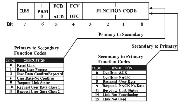
Control Field Bits in IEC 101 (Unbalanced Transmission)
In unbalanced transmission mode, the control field defines how the primary (master) and secondary (slave) stations communicate.
Each bit of this field carries specific operational meaning, ensuring proper frame sequencing, flow control, and link management.
| Code | Meaning | Description |
|---|---|---|
| PRM | Primary Message | 1 → Frame sent from the primary or initiating station |
| FCB | Frame Count Bit | Alternates between 0 and 1 for sequential frames to maintain synchronization |
| FCV | Frame Count Valid | 1 → FCB is valid; 0 → FCB is ignored |
| RES | Reserved | Always 0 |
| DFC | Data Flow Control Bit | Set to 1 by a secondary station if additional data would cause buffer overflow |
| ACD | Access Demand Bit | Set to 1 if Class 1 data is waiting to be transmitted |
The PRM, FCB, and FCV bits are managed by the controlling (master) station, while ACD and DFC bits are typically managed by the controlled (slave) stations.
Together, these bits ensure synchronized, reliable, and collision-free communication in IEC 60870-5-101 systems.
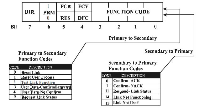
Control Field Bits in IEC 101 (Balanced Transmission)
In balanced transmission mode, both stations can initiate communication, meaning either end can send commands or data without waiting for a poll.
This mode is typically used for point-to-point or redundant communication links between two intelligent devices.
The control field structure for balanced transmission adds a direction bit (DIR) to indicate the flow of communication, while other bits are similar to the unbalanced mode.
| Code | Meaning | Description |
|---|---|---|
| DIR | Direction of Message | 1 → Message from A to B0 → Message from B to A |
| PRM | Primary Message | 1 → Frame from the primary or initiating station |
| FCB | Frame Count Bit | Alternates between 0 and 1 for sequential frames |
| FCV | Frame Count Valid | 1 → FCB is valid0 → FCB ignored |
| RES | Reserved | Always 0 |
| DFC | Data Flow Control Bit | Set to 1 by secondary station if more user data would cause buffer overflow |
How It Works:
- DIR defines the communication direction, ensuring both stations understand who initiated the exchange.
- PRM, FCB, and FCV maintain message sequencing and validation, while DFC ensures flow control.
- Since both sides can send data, balanced links require careful timing and buffer management to avoid collisions.
This setup allows bidirectional data exchange in real time, making it ideal for redundant SCADA controllers, peer-to-peer systems, and point-to-point RTU links where both devices can act as masters.
ASDU (Application Service Data Unit) in IEC 60870-5-101
The Application Service Data Unit (ASDU) is the core information block inside every variable-length IEC 60870-5-101 frame.
It carries the actual process data, commands, or status information exchanged between the controlling and controlled stations.
The ASDU starts immediately after the Link Address field and ends before the checksum.
Each ASDU contains a fixed-order header followed by one or more Information Objects.
ASDU Structure
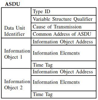
| Field | Size (bytes) | Description |
|---|---|---|
| Type Identification (Type ID) | 1 | Defines the kind of data or command (e.g., single-point info, measured value, interrogation). |
| Variable Structure Qualifier (VSQ) | 1 | Specifies the number of information objects and whether they are sequential. |
| Cause of Transmission (COT) | 2 or 3 | Indicates why the message is sent (e.g., spontaneous, activation, request). May include the Originator Address if used. |
| Common Address of ASDU (CA) | 1 or 2 | Identifies the source or destination RTU or station. |
| Information Object Address (IOA) | 1–3 | Points to the exact process data point or command target. |
| Information Elements (Data) | Variable | Contains the actual values, qualities, timestamps, or control parameters. |
Common ASDU Type IDs
| Type ID | Description | Direction |
|---|---|---|
| 1 (M_SP_NA_1) | Single Point Information | Monitoring |
| 3 (M_DP_NA_1) | Double Point Information | Monitoring |
| 9 (M_ME_NA_1) | Measured Value, Normalized | Monitoring |
| 45 (C_SC_NA_1) | Single Command | Control |
| 46 (C_DC_NA_1) | Double Command | Control |
| 100 (C_IC_NA_1) | General Interrogation Command | Control |
| 103 (C_CS_NA_1) | Clock Synchronization Command | Control |
Each Type ID defines how the data portion is structured and interpreted.
How the ASDU Works in Communication
- The master station sends ASDUs containing control commands (e.g., C_SC_NA_1).
- The RTU or substation replies with ASDUs containing confirmation or status data (e.g., M_SP_NA_1).
- The Cause of Transmission (COT) field ensures both sides know why the message was sent — whether it’s spontaneous, requested, or in response to a command.
The ASDU structure allows consistent and interoperable data exchange, making IEC 60870-5-101 suitable for complex SCADA environments with mixed vendor devices.
Time Tag in IEC 60870-5-101 ASDU
The Time Tag (also called Timestamp) in IEC 60870-5-101 adds precise timing information to data within an ASDU.
It allows the receiving station to know exactly when an event occurred or a measurement was taken, which is critical for sequence-of-events (SOE) recording, fault analysis, and synchronization in SCADA systems.
Not all ASDUs include a timestamp — only those Type IDs designed for time-tagged information, such as event reports or time-synchronized measurements.
Time Tag Types
IEC 60870-5-101 defines two main time tag formats:
| Time Format | Name | Size | Accuracy | Typical Use |
|---|---|---|---|---|
| CP24Time2a | Short Time Tag | 3 bytes | Millisecond + minute | Fast periodic data (no date) |
| CP56Time2a | Full Time Tag | 7 bytes | Millisecond + minute + hour + day + month + year | Event and historical data |
Both formats are transmitted in binary-coded decimal (BCD) or binary format, depending on implementation, and use little-endian (LSB first) ordering as per IEC 60870-5-4.
CP24Time2a – 3-Byte Time Tag
| Field | Size (bits) | Description |
|---|---|---|
| Milliseconds | 16 | Milliseconds (0–59999) |
| Minutes | 8 | Minutes (0–59) |
Use case:
Short time tagging for periodic updates or cyclic data where the date and hour are already known from system context.
CP56Time2a – 7-Byte Time Tag
| Field | Size (bits) | Description |
|---|---|---|
| Milliseconds | 16 | 0–59999 ms |
| Minutes | 8 | 0–59 |
| Hours | 8 | 0–23 |
| Day of Month + Day of Week | 8 | Day (1–31) + optional weekday |
| Month | 8 | 1–12 |
| Year | 8 | 0–99 (offset from 2000) |
Use case:
Detailed timestamping for spontaneous events, alarms, or time-tagged measurements (M_SP_TB_1, M_ME_TD_1, etc.).
Time Tag Usage in ASDUs
Not all ASDUs contain time tags — they’re present only in time-tagged variants of standard Type IDs.
For example:
| Type ID | Description | Time Tag Format |
|---|---|---|
| M_SP_TB_1 | Single Point Information with Time Tag | CP56Time2a |
| M_DP_TB_1 | Double Point Information with Time Tag | CP56Time2a |
| M_ME_TD_1 | Measured Value with Time Tag | CP56Time2a |
| C_CS_NA_1 | Clock Synchronization Command | CP56Time2a (in control direction) |
These time-tagged ASDUs are used to ensure chronological accuracy of event data and to synchronize field devices with the master clock.
Time Synchronization in IEC 101 Networks
Time synchronization across the network is typically performed using Type ID 103 (C_CS_NA_1) — the Clock Synchronization Command.
The master periodically sends the current time to all RTUs, which then use it to align their internal clocks.
Accurate time tagging allows SCADA operators to:
- Correlate events from multiple RTUs
- Analyze disturbances in chronological order
- Reconstruct system states before and after faults
Conclusion
The IEC 101 frame format is the foundation of reliable telecontrol communication.
By understanding how fixed and variable-length frames are structured, engineers can accurately interpret messages, verify network integrity, and debug communication issues in SCADA systems.
For quick and accurate analysis of real-world data, use our Free IEC 60870-5-101 Frame Decoder to automatically detect:
- All IOA and data elements
- Frame type (fixed or variable)
- ASDU boundaries and Type ID
- Cause of Transmission (COT)
- Originator Address and Common Address