DNP3 (Distributed Network Protocol) messages are built in multiple layers to ensure reliable communication between master stations and outstations (RTUs or IEDs) in SCADA systems.
Each layer adds its own control information, creating a message that can be verified, retransmitted, and correctly interpreted across noisy or unreliable communication links.
Table of Contents
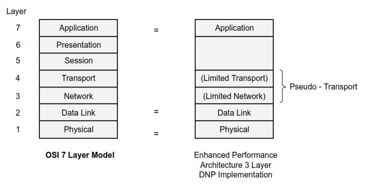
The Enhanced Performance Architecture (EPA)
DNP3 follows the IEC Enhanced Performance Architecture (EPA) model — a simplified 3-layer version of the OSI model consisting of:
| Layer | Function |
|---|---|
| Application Layer | Creates and interprets SCADA commands and data. |
| Data Link Layer | Frames messages, handles addressing, and provides error detection. |
| Physical Layer | Defines the medium (RS-232, Ethernet, radio, etc.) and signal transmission. |
DNP3 also adds a pseudo-transport layer, which handles segmentation and reassembly of large messages.
Message Buildup Process
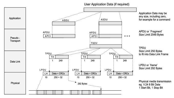
When a DNP3 message is sent, it passes downward through the layers:
- Application Layer: Creates the Application Protocol Data Unit (APDU) — the core data and commands.
- Pseudo-Transport Layer: Splits large APDUs into smaller Transport Protocol Data Units (TPDUs), each with a 1-byte header.
- Data Link Layer: Adds a 10-byte header and CRC checks to form Link Protocol Data Units (LPDUs).
- Physical Layer: Converts the data into a serial or network bit stream for transmission.
Application Layer (APDU)
The Application Layer handles actual SCADA data and command exchanges.
It builds Application Service Data Units (ASDUs) and wraps them with control headers to form APDUs.
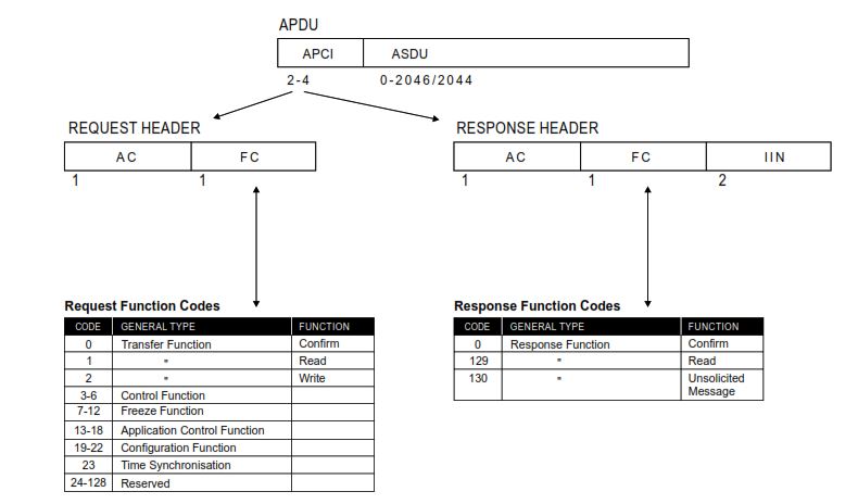
APDU Components:
| Field | Purpose |
|---|---|
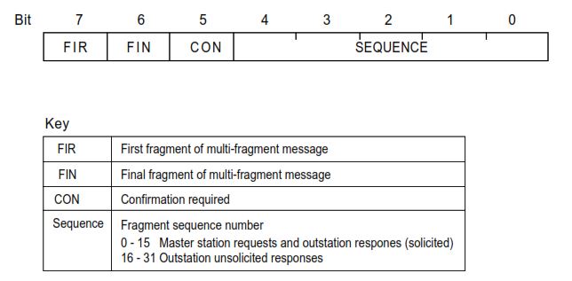
| Application Control (AC) | 1-byte field controlling flow (FIR, FIN, CON bits, and sequence number). |
| Function Code (FC) | Specifies the operation (READ, WRITE, SELECT, OPERATE, RESPONSE, etc.). |
| Data / ASDU | Contains DNP3 data objects (binary inputs, analogs, counters). |
| IIN (Internal Indications) | Used only in responses to report device status. |
Pseudo-Transport Layer
The pseudo-transport layer ensures large messages (up to 2048 bytes) can be divided into manageable fragments.
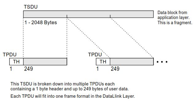
Each TPDU:
- Has a 1-byte header with:
- FIR (First Fragment)
- FIN (Final Fragment)
- 6-bit sequence counter (0–63)
- Carries up to 249 bytes of data, fitting exactly within one DNP3 frame.
This allows error detection and retransmission per frame rather than per large message.
Data Link Layer (Frame Format)
DNP3 uses the FT3 frame format (adapted from IEC 870-5-1).
Each frame contains a 10-byte fixed header and optional data blocks, each followed by a 16-bit CRC.
Standard DNP3 Frame Structure:

| Field | Bytes | Description |
|---|---|---|
| Start | 2 | Fixed 0x0564 pattern identifying frame start. |
| Length | 1 | Number of bytes following (excluding CRCs). |
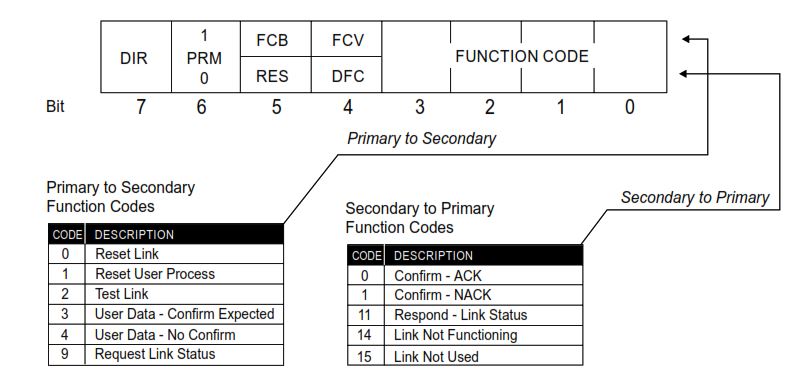
| Control | 1 | Contains direction, function, and frame count bits. |
| Destination Address | 2 | Receiving device address. |
| Source Address | 2 | Sending device address. |
| Header CRC | 2 | Error check for the header. |
| User Data | Up to 250 | Application data, divided into 16-byte blocks. |
| Block CRCs | 2 per block | Error check per 16-byte data block. |
Each frame may carry up to 250 bytes of data, giving a maximum total frame size of 292 bytes.
Error Detection and Reliability
DNP3 uses a 16-bit CRC (polynomial 0x3D65) for both headers and data blocks.
Every 16-byte block of data has its own CRC, allowing localized error correction.
If a CRC fails, the receiver discards the frame and requests retransmission.
Typical Message Example
Master Request → Outstation Response
| Step | Message |
|---|---|
| 1 | Master sends READ command (APDU) requesting binary inputs. |
| 2 | Transport layer divides it into TPDUs and frames. |
| 3 | Data Link layer adds FT3 headers, addressing, and CRCs. |
| 4 | Outstation receives, validates CRC, reassembles data, and responds with RESPONSE APDU. |
Summary
| Layer | Main Role | Data Unit | Max Size |
|---|---|---|---|
| Application | Commands & data | APDU | 2048 bytes |
| Pseudo-Transport | Fragmentation | TPDU | 250 bytes |
| Data Link | Framing & CRC | LPDU | 292 bytes |
| Physical | Transmission | Bit stream | — |
DNP3’s multi-layered structure, built with redundancy and CRC checking at every stage, ensures high reliability for SCADA communication — even over low-quality lines or radio links.