In Distributed Network Protocol (DNP3), the Internal Indications field—commonly known as IIN—plays a fundamental role in real-time SCADA diagnostics. Whether you’re troubleshooting substation RTUs, assessing communication integrity, or analyzing unsolicited events, DNP3 IIN bits provide the device’s internal status and operational health.
This article explains DNP3 IIN bits in depth, their function in DNP3, how Wireshark displays them, and how they impact SCADA reliability and cybersecurity.
Table of Contents
What Is the IIN Field in DNP3?
IIN stands for Internal Indication.
It is a 2-byte (16-bit) status field included in every DNP3 response message sent from an outstation/RTU to a master.
Purpose:
The DNP3 IIN bits are included in every DNP3 response message header. They tell the master about the status or needs of the outstation — such as available data, restart conditions, or trouble flags.
This information helps the master manage communication priorities, handle time resynchronization, and diagnose device health in real time.
Why IIN Matters in Industrial Systems
| Role | Explanation |
|---|---|
| Event monitoring | Indicates presence of Class 1/2/3 events for polling |
| Time integrity | Signals time sync requirements |
| Fault detection | Reports buffer overflows, device restarts, or trouble |
| Security | Detects unsolicited messages & abnormal behavior |
| Maintenance | Provides operational warnings & sync status |
Without reading IIN bits, DNP3 diagnostics is incomplete.
Structure of DNP3 IIN Bits (16-bit Field)
| Byte | Range | Purpose |
|---|---|---|
| IIN-LSB | Bits 0-7 | Communication & data conditions |
| IIN-MSB | Bits 8-15 | Device/system health & security |
Detailed IIN Bit Table
Low Byte (LSB — System & Event Alerts)
| Bit | Meaning When Set | Notes |
|---|---|---|
| 0 | All Stations Message Received | Set when an address in the range FFF0–FFFF is received. Cleared after the next response. Used to confirm that a broadcast message was received by this station. |
| 1 | Class 1 Data Available | Indicates that Class 1 event data is available. The master should request this data. |
| 2 | Class 2 Data Available | Indicates that Class 2 event data is available. |
| 3 | Class 3 Data Available | Indicates that Class 3 event data is available. |
| 4 | Time Synchronization Required | Set after a restart. Cleared once time synchronization is completed or when the master writes directly to the outstation IIN object. |
| 5 | Points in Local Mode | Set when one or more control points are in local control mode, meaning they cannot be operated remotely. |
| 6 | Device Trouble | Indicates an abnormal condition that cannot be represented by other IIN bits. Used as a general fault indicator. |
| 7 | Device Restart | Set when the user application or outstation restarts. Cleared when the master writes a 0 to this bit in the outstation IIN object. |
The First Byte of the Internal Indications (IIN) field provides the master station with key information about the operational status of an outstation (remote device).
It’s included in nearly every response message that an outstation sends to the master.
These bits allow the outstation to “communicate its needs” without requiring separate messages — improving efficiency and reliability.
High Byte (MSB — Device Status & Configuration)
| Bit | Meaning When Set | Notes |
|---|---|---|
| 0 | Function Code Not Implemented | The received function code is not supported by this outstation. |
| 1 | Requested Objects Unknown | The requested objects do not exist or are not defined in the specified class. |
| 2 | Parameters Invalid | One or more parameters in the qualifier, range, or data fields are invalid or out of range. |
| 3 | Buffer Overflow | An event buffer or other application buffer has overflowed — some data may have been lost. |
| 4 | Operation Already in Progress | A previous operation is still being executed; the requested one cannot start yet. |
| 5 | Corrupt Configuration | Indicates that the device’s configuration is corrupt or invalid — the master may need to re-download configuration data. |
| 6 | Reserved (0) | Always returns 0. Reserved for future use. |
| 7 | Reserved (0) | Always returns 0. Reserved for future use. |
The Second Byte IIN bits alert the master to application-level problems such as unsupported functions, invalid object requests, or buffer limitations.
When these bits are set in a DNP3 response APDU, they help the master station diagnose communication issues and take corrective actions — such as reissuing a request, synchronizing configuration, or clearing buffers.
Wireshark DNP3 IIN Bits Decode Example — Interpreting Internal Indications
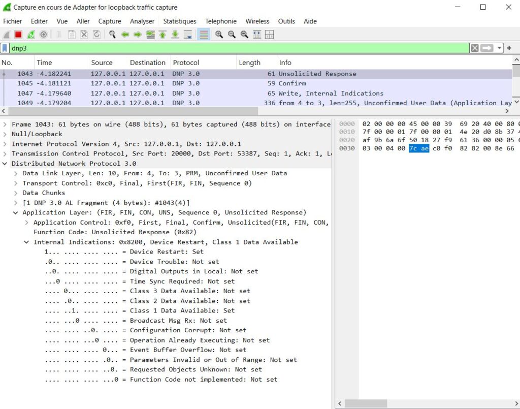
This Wireshark capture shows a DNP3 Unsolicited Response with an Internal Indications value of 0x8200. In this decode, the analyzer identifies two active IIN bits:
- Device Restart — the outstation has rebooted, signaling a possible power cycle, firmware update, or fault condition
- Class 1 Data Available — high-priority event data is waiting to be polled by the master SCADA system
All other IIN status bits, including time synchronization request, configuration error, unauthorized access, and buffer overflow, are not set.
This real DNP3 IIN decoding example illustrates how Wireshark makes it easy for engineers to detect device restarts, event notifications, and potential SCADA communication issues by analyzing internal indication bits. Understanding DNP3 IIN bits is essential for troubleshooting DNP3 networks, validating RTU behavior, and improving substation cybersecurity monitoring.
Conclusion
The IIN field is not optional — it’s essential for SCADA reliability, SOE accuracy, time integrity, and ICS cybersecurity. Understanding and decoding IIN bits allows operators to maintain system health, detect anomalies, and ensure reliable automation.
Try our Online DNP3 IIN & Frame Decoder to instantly decode:
- IIN flags
- Function codes
- Data object variations
- Time stamps
- Sequence & control fields