Modbus TCP/IP represents one of the most widely adopted industrial communication protocols in the automation world. Developed as an extension of the classic Modbus protocol, Modbus TCP/IP leverages Ethernet networks to provide reliable, real-time communication between industrial devices. When combined with Arduino’s flexibility and cost-effectiveness, developers can create powerful industrial automation solutions that rival commercial offerings at a fraction of the cost.
This article explores the technical aspects of implementing Modbus TCP/IP communication on Arduino platforms, providing comprehensive guidance for both beginners and experienced developers looking to integrate these technologies.
The appeal of using Arduino for Modbus TCP/IP applications stems from several compelling factors. Arduino boards offer accessible hardware with extensive community support, making them ideal for prototyping and educational purposes. The availability of open-source Modbus libraries simplifies development significantly, while the platform’s flexibility allows for custom implementations tailored to specific project requirements.
Whether you need to monitor sensors, control actuators, or integrate legacy industrial equipment with modern networks, Arduino provides a solid foundation for building robust Modbus TCP/IP solutions.
Understanding the fundamentals of Modbus TCP/IP is essential before diving into implementation. The protocol operates on a client-server model where a master device initiates communication with slave devices. In the TCP/IP variant, Modbus messages are encapsulated within TCP packets, using port 502 as the default listening port.
This approach provides several advantages over traditional serial Modbus RTU, including faster transmission speeds, longer communication distances, and the ability to connect multiple devices on a single network. The TCP/IP layer handles packet routing, error detection, and connection management, while the Modbus application layer maintains the familiar function codes and data structures that industrial engineers have relied on for decades.
Table of Contents
Understanding the Modbus TCP/IP Protocol Structure
The Protocol Stack Architecture
Modbus TCP/IP builds upon the traditional Modbus protocol by adding a TCP/IP wrapper that enables Ethernet communication. The protocol stack consists of several distinct layers, each serving a specific purpose in the communication process. At the application layer, Modbus defines function codes that determine the type of operation being performed, such as reading coils, reading discrete inputs, reading holding registers, or writing single registers.
Above this layer, the MBAP header (Modbus Application Protocol) provides transaction identification, protocol identification, length information, and unit identification, enabling reliable communication over TCP/IP networks.
The TCP/IP layer handles the actual data transmission across the network infrastructure. When a Modbus TCP/IP message is sent, it travels through multiple protocol layers before reaching its destination. The application data is first wrapped with the MBAP header, creating a Modbus PDU (Protocol Data Unit).
This PDU is then placed into a TCP segment, which includes source and destination port numbers, sequence numbers, acknowledgment numbers, and various control flags. The TCP segment is subsequently encapsulated in an IP packet for network routing, and finally transmitted as Ethernet frames over the physical network medium.
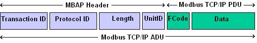
Understanding the MBAP header structure proves essential for proper implementation. The header consists of four distinct fields that precede every Modbus TCP/IP message. The Transaction Identifier occupies the first two bytes, serving as a unique identifier that allows clients to match requests with responses. The Protocol Identifier follows, typically set to zero for standard Modbus, though it can be used to distinguish between different protocols running on the same network. The Length field indicates the total number of bytes following this field, including the unit identifier and PDU data. Finally, the Unit Identifier allows the message to be routed to specific devices on serial networks bridged through TCP/IP gateways.
Modbus Function Codes and Data Types
The Modbus protocol defines numerous function codes that determine the operations clients can perform on servers. The most commonly used function codes include those for reading and writing discrete values and registers. Function code 01 (Read Coils) and function code 02 (Read Discrete Inputs) retrieve boolean data from the server, while function code 05 (Write Single Coil) and function code 15 (Write Multiple Coils) modify boolean output values. For analog data handling, function code 03 (Read Holding Registers) and function code 04 (Read Input Registers) provide access to 16-bit integer values, with function code 06 (Write Single Register) and function code 16 (Write Multiple Registers) enabling data modification.
Each data type in Modbus serves a specific purpose within industrial systems. Coils represent binary outputs that can be read and written, typically used for controlling digital outputs such as relays, LEDs, or solenoid valves. Discrete inputs are read-only binary values from sensors or input channels, providing status information about external conditions. Holding registers serve as general-purpose read/write storage for configuration parameters, setpoints, or computed values. Input registers function similarly but are read-only, commonly used for sensor readings, measured values, or status information that should not be modified by external clients.
The addressing scheme in Modbus follows a zero-based indexing system, though documentation often shows one-based notation. Registers are addressed using a 16-bit address space, allowing for up to 65,536 registers of each type. When implementing Modbus on Arduino, this addressing must be converted to the zero-based indexing used in array structures. Understanding this distinction prevents common errors in register mapping and ensures proper communication between devices. Many Modbus clients and servers use different conventions, making it essential to document the addressing scheme clearly for each implementation.
Hardware Requirements and Setup
Selecting the Appropriate Arduino Board
Choosing the right Arduino board for Modbus TCP/IP implementation depends on several factors including processing power, memory capacity, and network connectivity requirements. The Arduino UNO, while popular for general projects, often lacks sufficient memory and processing power for robust Modbus TCP/IP applications, especially when handling multiple concurrent connections or large data buffers. The Arduino MEGA offers significantly more SRAM and program memory, making it suitable for more complex implementations requiring extensive register maps or local data logging capabilities.
For Ethernet connectivity, developers can choose between several options depending on their requirements. The Arduino Ethernet Shield 2 provides a reliable wired Ethernet connection using the W5500 chip, offering good performance and broad library support. The Arduino MKR ETH Shield extends the MKR series with wired Ethernet capability, providing a compact solution with additional features like power over Ethernet support. For applications requiring wireless connectivity, the Arduino MKR WiFi 1010 or ESP32-based boards offer integrated WiFi with adequate processing power for Modbus TCP/IP communication. When selecting a board, consider the total memory footprint of your application, the number of Modbus registers you need to manage, and the expected communication load on your network.
Power considerations play a crucial role in industrial Modbus implementations. Industrial environments often require stable power delivery with appropriate filtering and protection against electrical noise. Using a quality power supply with adequate current capacity and proper grounding helps ensure reliable communication. For remote installations, consider boards with built-in voltage regulation and transient protection. Additionally, the Ethernet interface should be protected against ESD and electrical surges that can occur in industrial settings. Industrial-rated Ethernet switches with proper shielding and grounding provide better reliability than consumer-grade networking equipment.
Network Configuration and Cabling
Proper network configuration forms the foundation of reliable Modbus TCP/IP communication. The default port 502 should be configured on your network firewall to allow Modbus traffic. For testing purposes, ensure your computer and Arduino share the same network subnet, or configure port forwarding if communicating across network boundaries. Static IP addressing proves more reliable than DHCP for industrial applications, eliminating the risk of IP address changes that could disrupt communication. Document your IP addressing scheme and ensure all devices have unique addresses within the network.
Ethernet cabling requirements follow standard Cat5e or Cat6 specifications for most industrial applications. For environments with significant electromagnetic interference, shielded cable with proper grounding provides better noise immunity. Cable runs should be kept within the 100-meter limit specified for standard Ethernet, with longer distances requiring network repeaters or fiber optic converters. Industrial Ethernet switches with managed features like VLANs and Quality of Service (QoS) can improve performance by isolating Modbus traffic and prioritizing critical communications.
Network topology significantly impacts system reliability and performance. A star topology, where each device connects directly to a central switch, provides the best fault isolation and makes troubleshooting easier. Daisy-chain or ring topologies can reduce cable runs in some installations but may create single points of failure. For critical applications, consider redundant network paths with managed switches that can reroute traffic in case of cable failure. Understanding your network topology helps identify potential issues before they cause system-wide communication failures.
Software Libraries and Development Environment
Essential Modbus TCP/IP Libraries for Arduino
The Arduino ecosystem offers several well-established libraries for implementing Modbus TCP/IP communication. The ModbusIP library provides a straightforward implementation supporting both master and slave functionality with the Ethernet shield. It offers a clean API that abstracts the protocol details, allowing developers to focus on application logic. The library handles connection management, message framing, and CRC validation, presenting a simple interface for reading and writing registers. For more advanced applications, the library supports multiple concurrent connections, enabling an Arduino to act as both a client and server simultaneously.
The Arduino Modbus library, maintained as part of the official Arduino ecosystem, offers another robust option for Modbus TCP/IP implementation. This library provides separate classes for TCP and serial Modbus, with consistent APIs across communication types. The library implements the most common function codes and includes examples demonstrating various use cases. Its object-oriented design promotes clean code organization and simplifies maintenance of larger projects. The library’s active development community ensures regular updates addressing bugs and adding new features.
For applications requiring RTU protocol support alongside TCP, the ModbusMaster library provides comprehensive coverage of both protocols. This library excels in gateway applications where an Arduino bridges between serial RTU devices and TCP/IP networks. While slightly more complex than TCP-only libraries, it offers greater flexibility for hybrid implementations. The library’s source code is well-documented, making it easier to understand the underlying protocol mechanics and troubleshoot issues when they arise.
Setting Up the Arduino IDE for Modbus Development
Installing and configuring the Arduino Integrated Development Environment properly prepares your system for Modbus TCP/IP development. Begin by downloading the latest Arduino IDE from the official Arduino website, ensuring you have version 1.8.x or later for best compatibility with current libraries. The Arduino IDE 2.0 series offers improved library management and a modern interface, though the classic 1.8.x version remains widely supported. Install the IDE following the standard installation procedure for your operating system, and verify the installation launches successfully before proceeding.
Installing Modbus libraries through the Arduino Library Manager simplifies dependency management. Open the Arduino IDE and navigate to Sketch > Include Library > Manage Libraries. In the library manager, search for “ModbusIP” or “Arduino Modbus” to find the available libraries. Review the library descriptions, version numbers, and installation counts to select well-maintained options. Click Install to add the library to your Arduino environment. The library manager handles dependency resolution automatically, installing any required supporting libraries. After installation, verify the library appears in your installed libraries list and check that the example sketches are available through File > Examples.
Configuring board support for your specific Arduino variant completes the development environment setup. If using boards beyond the standard Arduino lineup, such as the ESP32 or STM32 variants, you may need to install additional board definitions through the Board Manager. Navigate to Tools > Board > Board Manager and search for your board type. Install the appropriate board package, then select your specific board from the Tools > Board menu. Proper board selection ensures your sketches compile for the correct processor architecture and enable board-specific features like enhanced memory management or hardware peripherals.
Implementing Modbus TCP/IP Client (Master) on Arduino
Establishing Network Connections
Creating a Modbus TCP/IP client on Arduino begins with establishing a reliable Ethernet connection. The initialization process involves configuring the Ethernet shield with appropriate network parameters and verifying the connection status before attempting Modbus communication. Initialize the Ethernet client object and attempt to connect to the target server using its IP address and the standard Modbus port 502. Implement connection retry logic to handle temporary network disruptions gracefully, with exponential backoff to prevent overwhelming the network during extended outages.
Connection state management proves critical for reliable master operation. Track the connection state explicitly, distinguishing between disconnected, connecting, connected, and error states. Implement a state machine that governs when to attempt connections, when to send requests, and when to initiate reconnections. This approach provides predictable behavior and simplifies debugging by making the current operational state clear. Include watchdog timer functionality to detect unresponsive servers and trigger appropriate recovery actions.
Network timeout configuration requires balancing responsiveness with robustness. Set connection timeouts appropriate for your network infrastructure, typically ranging from one to five seconds for local network communication. Longer timeouts may be necessary for wide-area or heavily congested networks, but they reduce system responsiveness. Implement both connect timeouts and response timeouts, as these represent different failure modes requiring different handling. When timeouts occur, log the event for troubleshooting purposes and attempt reconnection according to your defined recovery strategy.
Reading Data from Modbus Servers
Reading data from Modbus servers involves constructing appropriate read requests and processing the responses. The basic read operation uses function codes like 03 (Read Holding Registers) or 04 (Read Input Registers) to retrieve numeric data from the server. Specify the starting register address and the number of registers to read, then send the request to the server. Upon receiving a response, validate the response length and function code to ensure the data is valid before processing the register values.
Processing response data requires understanding the byte ordering conventions used by Modbus devices. Modbus specifies big-endian byte order for 16-bit registers, meaning the high byte precedes the low byte in the data stream. Some devices may use different conventions, particularly when representing 32-bit values across two consecutive registers. Implement byte-swapping logic to handle devices that use little-endian or mixed-endian representations. Document the byte order for each device you interface with, as inconsistencies between devices are a common source of communication errors.
Polling strategies determine how frequently you request data from servers and how you handle multiple servers. Simple polling approaches read each server sequentially with fixed intervals between reads. More sophisticated strategies adjust polling rates based on data change detection, reading faster when values are changing and slower when values are stable. For multiple servers, implement round-robin or priority-based scheduling to ensure critical devices receive attention promptly. Consider implementing background polling that continues while your main loop handles other processing tasks, using semaphore or flag mechanisms to synchronize data access.
Writing Data to Modbus Servers
Writing data to Modbus servers follows similar patterns to reading, with additional considerations for data validation and error recovery. Single register writes use function code 06 (Write Single Register), providing a straightforward way to set specific values. Multiple register writes use function code 16 (Write Multiple Registers) for efficient bulk updates. Before sending write requests, validate the data to prevent writing invalid values that could cause unexpected behavior in the target device.
Write verification improves reliability by confirming that written values were actually accepted by the server. After a write operation, read back the affected registers to verify the values were stored correctly. Implement verification logic that handles the case where verification fails, determining whether to retry the write, alert the operator, or take other appropriate action. Some applications may choose to skip verification for performance reasons, but this introduces risk of undetected write failures.
Coil and register writes use different function codes, with coils typically controlled using function code 05 (Write Single Coil) or function code 15 (Write Multiple Coils). Coil writes require boolean values, with 0xFF00 representing TRUE and 0x0000 representing FALSE per the Modbus specification. When implementing coil writes, ensure your code produces values conforming to this specification, as some devices may reject alternative representations. For binary control outputs like motor starters or valve actuators, coil writes provide direct control capability.
Implementing Modbus TCP/IP Server (Slave) on Arduino
Configuring Server Parameters
Implementing a Modbus TCP/IP server on Arduino requires defining the register map that the server will expose to clients. This map should reflect the actual data your application needs to share, organized logically for efficient access. Define distinct address ranges for different data types: holding registers for configurable parameters, input registers for measured values, coils for binary outputs, and discrete inputs for binary status signals. Keep the register map well-documented, as this documentation proves invaluable for clients connecting to your server.
The server configuration includes setting the unit identifier that clients will use to address your device. While TCP/IP addressing typically handles device identification, the unit identifier provides compatibility with serial Modbus gateways and certain client implementations that expect this field. Set a unique unit identifier for each device on your network, typically ranging from 1 to 247. Additionally, configure the server IP address, subnet mask, and gateway address appropriately for your network infrastructure, preferably using static IP assignment for reliability.
Memory management for the register map requires careful consideration on resource-constrained Arduino platforms. Allocate register arrays sized to your actual requirements, avoiding excessive memory consumption. Consider using PROGMEM for storing static data that doesn’t change during operation, freeing SRAM for dynamic values. For large register maps, implement paging or bank-switching schemes that allow accessing different register sets through overlapping address ranges. Monitor memory usage during development to ensure adequate headroom for stack operations and dynamic allocations.
Handling Client Requests
The server’s main loop handles incoming client connections and processes requests according to the Modbus protocol. Implement a connection acceptance routine that listens for incoming connections on port 502 and accepts them when detected. For each accepted connection, spawn handling logic that processes requests until the connection closes or a timeout occurs. The Arduino environment’s single-threaded nature requires non-blocking I/O and careful time management to prevent the server from blocking on slow operations.
Request processing extracts the function code from incoming messages and routes them to appropriate handlers. Each function code requires specific handling logic that validates the request parameters, performs the requested operation, and constructs the response. Invalid requests should receive appropriate exception responses, with exception codes indicating the nature of the error. Common exception codes include illegal function (01), illegal data address (02), and illegal data value (03), with server failure (04) used for errors that don’t fit other categories.
Response construction follows strict formatting rules defined by the Modbus protocol. The response must include the function code (with high bit set for exception responses), followed by data appropriate to the function code. Include the transaction identifier from the request in the response to enable clients to match responses with requests. Calculate and include any necessary length fields, and ensure the response fits within the maximum Modbus TCP message size of 260 bytes. For performance, pre-allocate response buffers rather than constructing messages dynamically.
Register Management Strategies
Effective register management involves synchronizing the physical or computed values with the register map that clients access. One approach uses direct mapping, where register arrays hold actual values that the application updates directly. This approach works well for values that change infrequently or where immediate consistency is required. Another approach uses shadow registers, where the Modbus registers reflect cached values updated periodically from underlying sources. This approach works better for slow-changing data or values that require time-consuming reads from sensors.
Value scaling and conversion often require attention when managing registers. Raw sensor values may need scaling to engineering units before being exposed through Modbus registers. Implement scaling functions that convert between raw and scaled representations, applying appropriate rounding and limiting to prevent overflow. For bidirectional conversions, ensure the scaling functions are exact inverses of each other to maintain consistency between values written and values subsequently read.
Thread safety and interrupt considerations affect register management on Arduino platforms. While Arduino lacks true multithreading, interrupt service routines can modify register values asynchronously. Protect shared data structures using atomic operations or by disabling interrupts during critical sections. Be cautious about calling library functions or performing lengthy operations within interrupt handlers, as this can cause timing issues. Design your application to minimize the code executed in interrupt context, using flags or circular buffers to transfer data to the main loop for processing.
Code Examples and Practical Implementations
Complete Modbus TCP Client Example
The following example demonstrates a complete Modbus TCP client implementation on Arduino with Ethernet connectivity. This sketch reads holding registers from a remote server and displays the values, serving as a foundation for more complex client applications.
#include <SPI.h>
#include <Ethernet.h>
#include <ModbusIP.h>

// Network configuration
byte mac[] = {0xDE, 0xAD, 0xBE, 0xEF, 0xFE, 0xED};
IPAddress server(192, 168, 1, 100);  // Modbus server IP
const uint16_t PORT = 502;           // Modbus TCP port

// Modbus IP object
ModbusIP modbusIP;

// Timing configuration
const unsigned long POLL_INTERVAL = 1000;  // ms between polls
unsigned long lastPoll = 0;

void setup() {
  Serial.begin(115200);
  while (!Serial) {
    ;  // Wait for serial port connection
  }

  // Initialize Ethernet with DHCP or static IP
  if (Ethernet.begin(mac) == 0) {
    Serial.println("DHCP failed, using static configuration");
    Ethernet.begin(mac, IPAddress(192, 168, 1, 50));
  }

  Serial.print("Arduino IP: ");
  Serial.println(Ethernet.localIP());
}

void loop() {
  // Maintain Ethernet connection
  switch (Ethernet.maintain()) {
    case RenewFail:
      Serial.println("Error: renewing DHCP lease failed");
      break;
    case RenewSuccess:
      Serial.println("Renewed DHCP lease");
      break;
    case RebindFail:
      Serial.println("Error: rebinding DHCP lease failed");
      break;
    case RebindSuccess:
      Serial.println("Rebound DHCP lease");
      break;
  }

  // Poll Modbus server at specified interval
  unsigned long currentMillis = millis();
  if (currentMillis - lastPoll >= POLL_INTERVAL) {
    lastPoll = currentMillis;

    // Create Modbus frame for reading holding registers (Function 03)
    uint16_t result = modbusIP.readHoldingRegisters(server, 1, 0, 2);

    if (result >= 0) {
      Serial.print("Register 0: ");
      Serial.println(modbusIP.getResponseBuffer(0));
      Serial.print("Register 1: ");
      Serial.println(modbusIP.getResponseBuffer(1));
    } else {
      Serial.print("Read failed, error code: ");
      Serial.println(result);
    }

    // Clear response buffer for next operation
    modbusIP.clearResponseBuffer();
  }
}
This implementation establishes an Ethernet connection, either through DHCP or static configuration, and performs periodic reads of holding registers from a remote Modbus server. The readHoldingRegisters function handles the protocol details internally, returning a status code indicating success or failure. When successful, the response buffer contains the retrieved register values. The code includes DHCP maintenance to handle lease renewals automatically, and implements polling with configurable intervals for efficient data acquisition.
Complete Modbus TCP Server Example
The complementary example implements a Modbus TCP server on Arduino, exposing a register map to network clients. This server manages simulated sensor data and control outputs, demonstrating the register handling patterns required for server implementations.
#include <SPI.h>
#include <Ethernet.h>
#include <ModbusIP.h>

// Network configuration
byte mac[] = {0xDE, 0xAD, 0xBE, 0xEF, 0xFE, 0xED};
IPAddress ip(192, 168, 1, 100);
const uint16_t PORT = 502;

// Modbus IP object
ModbusIP modbusIP;

// Register definitions
namespace ModbusRegisters {
  // Holding registers (read/write) - addresses 0-19
  uint16_t holdingRegisters[20] = {0};

  // Input registers (read-only) - addresses 0-19
  uint16_t inputRegisters[20] = {0};

  // Coils (read/write digital outputs) - addresses 0-79
  bool coils[80] = {false};

  // Discrete inputs (read-only digital inputs) - addresses 0-79
  bool discreteInputs[80] = {false};
}

void setup() {
  Serial.begin(115200);

  // Configure Ethernet with static IP
  Ethernet.begin(mac, ip);

  // Check Ethernet hardware status
  if (Ethernet.hardwareStatus() == EthernetNoHardware) {
    Serial.println("Ethernet shield not found");
    while (true) {
      delay(1);  // Halt
    }
  }

  if (Ethernet.linkStatus() == LinkOFF) {
    Serial.println("Ethernet cable not connected");
  }

  Serial.print("Server IP: ");
  Serial.println(Ethernet.localIP());
  Serial.print("Server Port: ");
  Serial.println(PORT);

  // Initialize some test values
  ModbusRegisters::holdingRegisters[0] = 1234;
  ModbusRegisters::holdingRegisters[1] = 5678;
  ModbusRegisters::inputRegisters[0] = 100;
  ModbusRegisters::inputRegisters[1] = 200;

  Serial.println("Modbus TCP Server initialized");
}

void loop() {
  // Update sensor simulation
  updateSensorData();

  // Process Modbus requests - must be called frequently
  modbusIP.task();

  delay(10);
}

void updateSensorData() {
  // Simulate sensor readings that change over time
  static unsigned long lastUpdate = 0;
  unsigned long currentMillis = millis();

  if (currentMillis - lastUpdate >= 1000) {
    lastUpdate = currentMillis;

    // Simulate temperature reading (scaled by 10, range 20.0-30.0°C)
    ModbusRegisters::inputRegisters[0] = random(200, 300);

    // Simulate pressure reading (scaled by 100, range 1.010-1.030 bar)
    ModbusRegisters::inputRegisters[1] = random(1010, 1030);

    // Update discrete inputs based on thresholds
    ModbusRegisters::discreteInputs[0] = (ModbusRegisters::inputRegisters[0] > 250) ? true : false;
    ModbusRegisters::discreteInputs[1] = (ModbusRegisters::inputRegisters[1] > 1020) ? true : false;

    // Increment counter in holding register
    ModbusRegisters::holdingRegisters[10]++;
  }
}
This server implementation configures the Arduino as a Modbus TCP server, initializing holding registers, input registers, coils, and discrete inputs that clients can access. The modbusIP.task() function handles incoming requests in the main loop, automatically routing them to appropriate handlers based on function code. The updateSensorData function demonstrates how to update register values dynamically, simulating sensor readings that change over time. Custom callback functions provide hooks for application-specific register handling logic.
Troubleshooting Common Issues
Network Connectivity Problems
Network connectivity issues represent the most common source of Modbus TCP/IP communication failures. When experiencing connection problems, begin by verifying basic network connectivity using ping or similar tools to confirm the Arduino is reachable on the network. Check the IP configuration matches your network’s addressing scheme, including subnet mask and gateway settings. Ensure the Ethernet cable is properly connected and the link indicator lights illuminate on both the Arduino Ethernet interface and the network switch.
Firewall and security settings frequently block Modbus traffic, especially on corporate networks. Verify that port 502 is open for both inbound and outbound traffic on any computers running Modbus client software. Some antivirus and security suites include network filtering that blocks unexpected traffic; temporarily disabling these can help isolate the issue. Industrial networks may implement VLANs or network segmentation that restricts communication between certain device groups; coordinate with network administrators to ensure proper network access for your devices.
IP address conflicts cause intermittent or complete communication failures. Scan your network for duplicate IP addresses using network scanning tools. When using DHCP, ensure the DHCP server has available addresses and that lease times are appropriate for your application. Static IP addressing provides more predictable behavior but requires careful address management to prevent conflicts. Document all static IP assignments and consider implementing address reservation in your DHCP server for devices that would otherwise use static addresses.
Protocol and Data Issues
Incorrect register addressing causes many data communication problems, as different systems use different conventions for register numbering. Some systems use zero-based addressing while others use one-based addressing; some count from zero while others count from one. When connecting to unfamiliar devices, experiment with different address offsets to determine the correct convention. Maintain documentation of the addressing scheme for each device you interface with, as inconsistencies between vendors are common.
Data type mismatches lead to misinterpreted values and incorrect system behavior. Verify that data types match between your Arduino implementation and connected devices. 32-bit integers typically span two consecutive registers, and byte ordering may differ between systems. Some devices store floating-point values in IEEE 754 format while others use proprietary formats; ensure you understand how each device represents complex data types. Implement appropriate conversion functions to handle differences in data representation.
Timeout and retry configuration affects both reliability and performance. Too-short timeouts cause unnecessary retries for legitimate slow responses, while too-long timeouts degrade system responsiveness. Consider the network characteristics of your installation when configuring timeouts; local networks typically allow shorter timeouts than wide-area or cellular connections. Implement intelligent retry logic that backs off progressively on repeated failures, preventing network congestion during extended outages.
Memory and Performance Optimization
Memory constraints on Arduino platforms require careful resource management, especially for applications with large register maps or multiple concurrent connections. Monitor SRAM usage during development using the techniques provided by the Arduino environment, ensuring adequate memory remains for stack operations and dynamic allocations. Minimize string usage in frequently-called functions, as string objects consume significant memory. Pre-allocate buffers and arrays rather than creating them dynamically during operation.
Performance optimization focuses on reducing communication overhead and processing time. Batch multiple register reads into single requests when possible, reducing the number of network round trips required. Implement caching strategies to avoid repeated reads of unchanged values. For server implementations, minimize processing time in the main loop by keeping request handlers efficient. Consider using hardware acceleration features available on certain Ethernet controllers to offload protocol processing from the main CPU.
Stack overflow and watchdog timer issues often manifest as intermittent failures or unexpected resets. The Arduino watchdog timer provides protection against infinite loops or hangs, automatically resetting the system if normal operation doesn’t resume within the configured timeout. Ensure your watchdog is properly fed during long operations, and avoid deep recursion that could exhaust stack space. Diagnose stack issues by examining variable values or implementing stack depth monitoring during development.
Advanced Applications and Best Practices
Building Multi-Device Networks
Complex industrial installations typically involve multiple Modbus devices communicating through a central controller or gateway. Designing such systems requires careful attention to network architecture, addressing schemes, and communication scheduling. Implement hierarchical communication patterns where a master controller communicates with multiple slaves, each with unique unit identifiers. Consider the communication patterns of your application when allocating addressing space, grouping related registers together to enable efficient batch operations.
Gateway implementations bridge between different Modbus variants or network segments. An Arduino can function as a protocol gateway, receiving Modbus TCP requests and forwarding them to serial RTU devices or vice versa. This approach enables integrating legacy serial devices into modern Ethernet-based systems. Gateway implementations require careful handling of protocol translation, including addressing, function code mapping, and data type conversion. Implement protocol-specific features like broadcast addressing or request queuing that differ between Modbus variants.
Redundant communication paths improve reliability for critical applications. Configure multiple communication routes to important devices, with automatic failover when primary paths fail. Implement heartbeat monitoring to detect device or path failures promptly. For extremely critical systems, consider dual-master configurations where two controllers share monitoring responsibilities, each capable of taking control if the other fails. Evaluate the added complexity against reliability requirements when designing redundant systems.
Security Considerations
Modbus TCP/IP was designed for industrial environments where security was not a primary concern, creating potential vulnerabilities in modern networked deployments. Implement network segmentation to isolate Modbus traffic from general corporate networks, using VLANs or physical separation to reduce attack surface. Firewalls should be configured to allow only necessary Modbus traffic, blocking unauthorized access attempts. Monitor network activity for unusual patterns that might indicate scanning or intrusion attempts.
Authentication and access control provide additional protection for sensitive applications. While standard Modbus lacks built-in authentication, implement application-layer security measures such as requiring specific register sequences before enabling write operations. Log all Modbus activity for audit purposes, including successful and failed access attempts. For highly sensitive applications, consider using encrypted communication channels or implementing Modbus over VPN connections.
firmware updates and configuration changes require appropriate security controls to prevent unauthorized modifications. Implement secure boot processes that verify firmware integrity before execution. Protect configuration interfaces with strong authentication mechanisms. Maintain secure backups of configuration data that can be used for recovery in case of corruption or compromise. Regularly update firmware and libraries to address known vulnerabilities as they are discovered and patched.
Testing and Deployment
Thorough testing validates correct operation before deployment in production environments. Develop test procedures that exercise all functionality, including normal operation, boundary conditions, and error handling. Create test fixtures that simulate connected devices, allowing repeatable testing without requiring physical hardware. Test network failures by temporarily disconnecting cables or blocking ports to verify recovery behavior. Include stress testing that exercises maximum expected load to identify performance limitations.
Deployment checklists ensure all configuration is complete and correct. Verify network settings match the target installation environment. Confirm all connected devices are reachable and properly configured. Document the installed configuration for future reference and troubleshooting. Establish monitoring and alerting to detect operational issues promptly. Plan for graceful degradation when failures occur, ensuring safe states for controlled shutdown if necessary.
Maintenance procedures maintain reliable operation over time. Establish schedules for reviewing logs and performance metrics to identify trends or emerging issues. Plan for firmware and library updates, testing them in controlled environments before applying to production systems. Maintain spare parts and replacement units to minimize downtime during hardware failures. Document lessons learned from operational issues and incorporate improvements into procedures and designs.
Conclusion
Implementing Modbus TCP/IP communication on Arduino platforms provides an accessible pathway to industrial automation for developers of all experience levels. The combination of Arduino’s flexible hardware ecosystem and the robust Modbus protocol enables creation of sophisticated monitoring and control systems at reasonable cost. Understanding the protocol fundamentals, proper hardware selection, and software implementation patterns covered in this article provides the foundation for successful projects.
The techniques and examples presented here represent starting points for your specific applications. Modbus TCP/IP implementations vary in their requirements, and the best approach depends on your particular use case, connected devices, and operational environment. The Arduino community offers extensive resources for troubleshooting and optimization, and the open-source nature of available libraries allows customization when standard implementations don’t meet your needs. Embrace iterative development, testing incrementally as you build your system, and don’t hesitate to refactor as your understanding of requirements deepens.
As industrial connectivity continues to evolve, Modbus TCP/IP remains relevant due to its simplicity, ubiquity, and proven reliability. Arduino’s role in this landscape continues to grow as the platform matures and gains acceptance in professional automation contexts. Whether you’re building educational prototypes, small-scale automation projects, or production systems, the skills developed through Modbus TCP/IP implementation on Arduino provide valuable expertise applicable across industrial automation careers.