
High availability is a mandatory requirement in modern industrial automation networks. Process control, power systems, water treatment plants, and safety-critical infrastructures cannot tolerate long communication interruptions.
Beacon Redundancy Protocol (BRP) is an Ethernet-based redundancy protocol standardized in IEC 62439-5. It provides deterministic fault detection and fast recovery against single point failures while keeping the network architecture simple and scalable.
Unlike switch-based redundancy protocols, BRP places the redundancy intelligence inside the end nodes, not the switches.
Table of Contents
BRP in the Context of IEC 62439
The IEC 62439 series defines multiple redundancy protocols for industrial Ethernet networks, each targeting different performance and architectural requirements.
Within this family:
- MRP (IEC 62439-2) focuses on ring topologies with switch-based redundancy.
- PRP and HSR (IEC 62439-3) provide seamless redundancy through frame duplication.
- BRP (IEC 62439-5) introduces end-node-based redundancy using beacon monitoring.
BRP is specifically designed for high-availability automation networks where:
- Standard Layer-2 Ethernet switches are preferred
- Redundancy decisions should not depend on switch logic
- Deterministic recovery times are required
- Large network topologies must be supported
Design Philosophy of Beacon Redundancy Protocol
The fundamental concept behind BRP is network duplication with distributed decision making.
Key principles include:
- Two redundant network infrastructures (Infrastructure A and Infrastructure B)
- End nodes connected to both infrastructures using dual Ethernet ports
- Only one port active at any given time
- End nodes independently detect failures and switch paths
- No protocol-specific functionality required in switches
This design eliminates the need for proprietary redundancy mechanisms inside the switching infrastructure and enables the use of standard IEEE 802.3 and IEEE 802.1 compliant switches.
Network Topologies Supported by BRP
BRP is flexible and supports multiple physical network topologies.
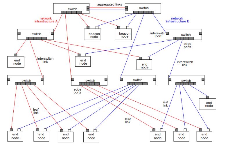
1. Star Topology
In a star topology:
- Two top-level switches form the core
- Beacon nodes are connected directly to the core switches
- Multiple access switches and end nodes are connected below
This topology is common in large plants and distributed control systems.
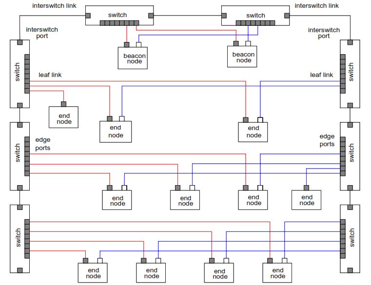
2. Linear Topology
Linear or daisy-chain topologies are frequently used in:
- Conveyor systems
- Pipelines
- Tunnel automation
BRP supports linear layouts while maintaining deterministic recovery.
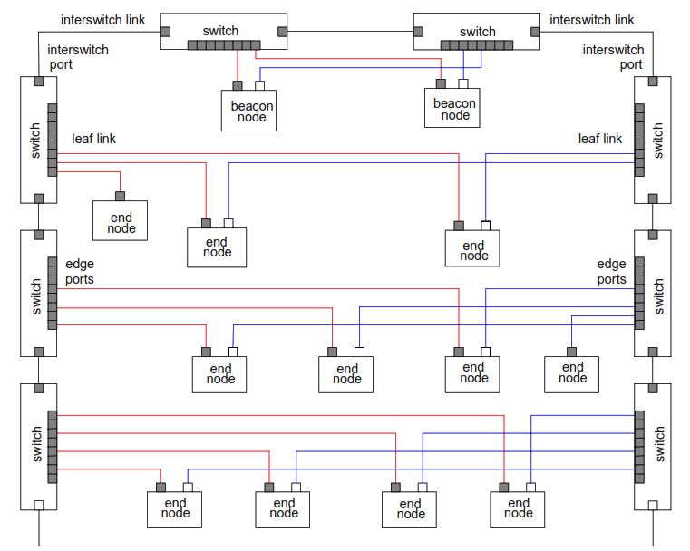
3. Ring Topology
BRP can also be used in ring topologies:
- Standard switches run RSTP to prevent loops
- BRP handles redundancy at the end-node level
- Switch-level loop prevention and end-node redundancy coexist
Beacon Redundancy Protocol Network Components
1. Ethernet Switches
Beacon Redundancy Protocol networks use standard Ethernet switches that:
- Comply with IEEE 802.1D and IEEE 802.1Q
- Support MAC address learning and filtering
- Treat multicast traffic as broadcast
No BRP awareness or configuration is required in the switches.
2. End Nodes
Doubly Attached Nodes (DANB)
A DANB:
- Has two physical Ethernet ports (Port A and Port B)
- Uses a single MAC address
- Actively communicates on only one port at a time
- Implements the BRP protocol state machine
Beacon End Nodes
Beacon nodes are special DANBs that:
- Are connected directly to top-level switches
- Periodically transmit beacon messages
- Act as reference points for network health monitoring
- Participate in path verification procedures
Singly Attached Nodes
Single-port devices:
- Do not implement BRP
- Can coexist with BRP nodes
- Communicate normally within the network
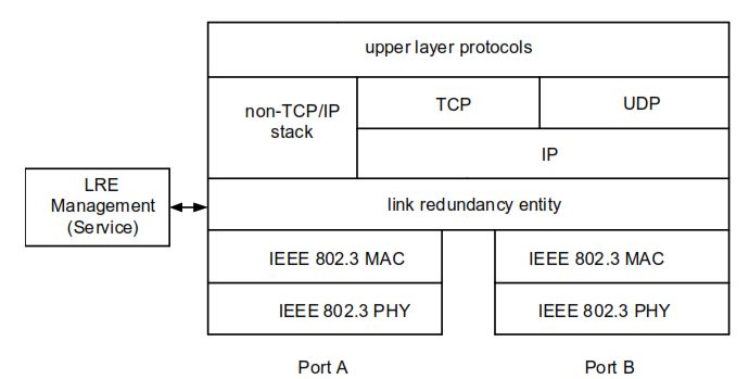
Beacon Redundancy Protocol Stack Architecture
Beacon Redundancy Protocol operates at Layer 2 of the OSI model and integrates cleanly into the Ethernet stack.
Each BRP end node contains:
- Two IEEE 802.3 PHY interfaces
- A single MAC entity
- A Link Redundancy Entity (LRE)
The LRE is responsible for:
- Monitoring link status
- Processing beacon messages
- Managing fault detection timers
- Switching the active port
- Generating BRP protocol messages
Upper-layer protocols such as IP, TCP, UDP, and application protocols remain unchanged and unaware of redundancy events.
Beacon Mechanism and Fault Detection
The beacon mechanism is the core innovation of Beacon Redundancy Protocol.
1. Beacon Transmission
Beacon end nodes periodically transmit beacon messages:
- Default transmission interval: 450 µs
- Sent as multicast Ethernet frames
- High priority VLAN tagging (priority 7)
2. Beacon Monitoring
Each BRP end node monitors beacon reception on:
- Active port
- Inactive port
If beacon messages fail to arrive on the active port within the configured timeout, the node assumes a failure in the active network path.
3. Beacon Timeout
The default timeout is configured so that:
- At least two beacon messages must be lost
- False positives are avoided
- Detection remains deterministic
Fault Detection Mechanisms in BRP
Beacon Redundancy Protocol combines multiple fault detection methods to ensure complete coverage.
1. Link Fault Detection
Physical layer monitoring detects:
- Cable breaks
- Port failures
- Local hardware faults
Recovery from link faults can occur in less than 10 µs.
2. Receive Path Fault Detection
Beacon monitoring detects:
- Switch failures
- Infrastructure outages
- Downstream connectivity loss
Typical recovery time is less than 1 ms.
3. Transmit Path Fault Detection
Some failures affect only the transmit direction and are not detectable by physical link status. BRP addresses this using:
- Failure_Notify messages
- Path_Check_Request messages
- Path_Check_Response messages
This mechanism ensures detection of asymmetric and silent failures.
Beacon Redundancy Protocol Protocol Messages
Beacon Redundancy Protocol uses a dedicated EtherType and a set of well-defined message formats.
- EtherType: 0x80E1
- Multicast MAC: 01-15-4E-00-02-01
- VLAN Priority: 7
1. Beacon Message
- Periodic heartbeat
- Includes sequence ID and timeout value
- Broadcast to entire network
2. Learning_Update Message
- Sent immediately after a port switchover
- Forces switches to update MAC address tables
- Enables rapid restoration of unicast traffic
3. Failure_Notify Message
- Sent when expected traffic from a node is missing
- Alerts the transmitting node of a potential path failure
4. Path_Check_Request and Path_Check_Response
- Used to verify the integrity of transmit paths
- Exchanged between end nodes and beacon nodes
- Trigger port switching when responses are missing
End Node State Machine
BRP end nodes operate according to a deterministic state machine defined in IEC 62439-5.
Key states include:
- INITIALIZATION
- IDLE
- PORT_A_ACTIVE
- PORT_B_ACTIVE
- FAULT
State transitions are triggered by:
- Link status changes
- Beacon reception or loss
- Timer expiration
- Path check results
This deterministic behavior ensures predictable network recovery.
Beacon End Node State Machine
Beacon nodes follow a similar state machine but include additional behavior:
- Periodic beacon transmission
- Participation in path verification for other nodes
- Independent port switching
If one beacon node fails, the network remains operational using the remaining beacon node.
Port Switchover and Active Port Swap
Beacon Redundancy Protocol normally operates with one active port per node. However, to ensure long-term reliability, BRP includes a periodic active port swap mechanism.
- Default swap period: 1 hour
- Ensures both network infrastructures are tested
- Detects dormant faults on inactive paths
- Improves overall availability
Fault Recovery Time Analysis
Beacon Redundancy Protocol defines a deterministic worst-case fault recovery time:
tfr = tnr + tid + tpcrWhere:
- tnr = Node receive timeout
- tid = Infrastructure propagation delay
- tpcr = Path check request timeout
In large networks (hundreds of nodes), typical worst-case recovery times are in the range of 4–5 ms, which is acceptable for most industrial automation systems.
Beacon Redundancy Protocol Management and Diagnostics
Beacon Redundancy Protocol includes a management interface allowing:
- Configuration of node parameters
- Retrieval of port status
- Monitoring of fault conditions
- Integration with diagnostic tools
Supported services include:
- Set_Node_Parameters
- Get_Node_Parameters
- Add_Node_Receive_Parameters
- Remove_Node_Receive_Parameters
- Get_Node_Status
This enables centralized supervision and maintenance planning.
Advantages of Beacon Redundancy Protocol
Beacon Redundancy Protocol offers several technical advantages:
- Deterministic fault recovery
- No specialized switches required
- High scalability
- Compatibility with standard Ethernet
- Suitable for brownfield installations
- Distributed redundancy decisions
Limitations and Design Considerations
Despite its strengths, Beacon Redundancy Protocol has some limitations:
- Requires dual-port end nodes
- Slight communication interruption during switchover
- Less vendor support compared to PRP/HSR
- More complex end-node implementation
These factors must be evaluated during system design.
Typical Application Areas
Beacon Redundancy Protocol is well suited for:
- Process automation systems
- Power generation and distribution
- Water and wastewater treatment
- Oil and gas facilities
- Manufacturing and assembly lines
- Industrial monitoring networks
Conclusion
Beacon Redundancy Protocol (BRP) provides a powerful and standards-based solution for building high-availability industrial Ethernet networks without relying on proprietary switching hardware. By combining beacon-based fault detection, distributed end-node intelligence, and deterministic recovery behavior, BRP meets the demanding requirements of industrial automation environments defined in IEC 62439-5.
For systems where predictable recovery times, scalability, and standard Ethernet compatibility are critical, BRP remains a technically sound and robust redundancy option.