Key takeaways
- Learn how to configure and fine-tune IEC 60870-5-104 timeout values t0–t3 for reliable SCADA communication and link supervision.
- Focus protocol: IEC-104 — see the reference page for frame format, OSI layer, and port/ethertype details.
- Related topics: Timeout Values, IEC 104, t0, t1.
- Read time: 5 · 997 words · published .
Reliable communication in IEC 60870-5-104 depends heavily on properly tuned timeout parameters.
The standard defines several timing constants — t0, t1, t2, and t3 — which control connection setup, data acknowledgment, and link supervision between the controlling station (master) and the controlled station (slave/RTU).
Misconfigured timeouts can cause link resets, delayed data updates, or even total communication failure.
- What Are Timeout Parameters in IEC 104?
- Overview of the Four Timeout Parameters
- Detailed Explanation of Each Timeout
- How These Timers Interact
- Example Configuration
- Testing and Optimization Steps
- Common Timeout-Related Issues
- Best-Practice Recommendations
- Next Step: Decode & Test Your IEC 104 Frames
What Are Timeout Parameters in IEC 104?
Timeouts are timing thresholds that determine how long a device waits for a response or activity before taking corrective action.
In IEC 104 (built on TCP/IP), these values ensure that both sides maintain synchronized communication sessions.
IEC 104 inherits these concepts from IEC 60870-5-101, adapting them for network-based communication instead of serial links.
Overview of the Four Timeout Parameters
| Parameter | Meaning | Typical Range (s) | Default Example |
|---|---|---|---|
| t0 | Connection establishment timeout — time allowed for TCP + IEC 104 link setup. | 10–30 | 30 s |
| t1 | Acknowledgment timeout — time to wait for acknowledgment of an I-format APDU. | 10–60 | 15 s |
| t2 | Acknowledgment delay — time before sending an acknowledgment when no I-format APDUs are received. | 1–10 | 5 s |
| t3 | Idle supervision timeout — maximum idle period before sending a TEST FR ACT to confirm link activity. | 20–300 | 25 s |
Detailed Explanation of Each Timeout
1. t0 – Connection Establishment Timeout
- Starts when a station attempts to open the TCP session.
- If no response is received before t0 expires, the connection is considered failed.
- Typical cause of timeout: network issues, port blocking, or unresponsive RTU.
Tip:
- Use longer t0 for high-latency or VPN links (e.g., 30–60 s).
- For LAN or fiber connections, 10 s is sufficient.
2. t1 – I-Format Acknowledgment Timeout
- Applies after sending an I-format APDU (data frame).
- If acknowledgment (S-format or I-format) is not received within t1, the sender closes and reopens the connection.
- This is the most critical timeout affecting communication reliability.
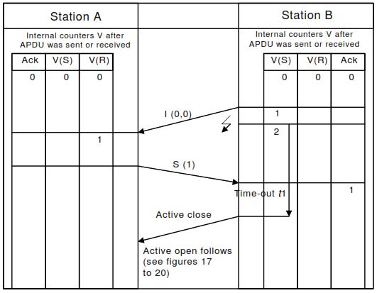
t1 – I-Format Acknowledgment Timeout
Example:
- If t1 = 15 s and an RTU is temporarily busy, the master may prematurely disconnect.
- Increasing t1 to 30 s often resolves “frequent reconnect” issues.
3. t2 – Acknowledgment Delay Timer
- When no new data arrives, t2 defines the delay before the receiver sends a standalone S-format acknowledgment.
- Prevents unnecessary acknowledgments when data flow is continuous.
- If t2 expires without new I-frames, the receiver sends an acknowledgment to keep the session active by an S format APDU.
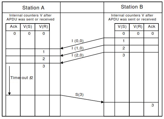
t2 – Acknowledgment Delay Timer
Tuning:
- Too short → extra network traffic.
- Too long → possible t1 expiry on the sender. Keep t2 < t1 / 2 as a rule of thumb.
4. t3 – Idle Supervision Timer
- Supervises the link during idle periods.
- When t3 expires, the controlling station sends a TEST FR ACT (U-frame) to confirm the session is alive.
- The controlled station must respond with TEST FR CON.
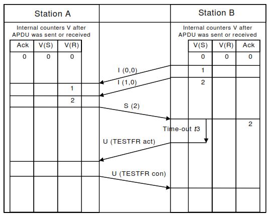
t3 – Idle Supervision Timer
Use:
- Maintains heartbeat in low-traffic networks and detects silent disconnections.
- Common settings: 20 – 120 s.
How These Timers Interact
- t1 > t2 > network delay
- t3 ≫ t1 (usually 2–4× t1)
- t0 > t1 + t2 (for establishing before watchdogs fire)
Proper proportioning prevents unnecessary resets and ensures smooth TCP keep-alive behavior.
Example Configuration
| Scenario | Network Type | t0 | t1 | t2 | t3 |
|---|---|---|---|---|---|
| Control Center ↔ RTU via LAN | Fiber or local Ethernet | 10 s | 15 s | 5 s | 25 s |
| Regional SCADA ↔ Remote RTU (4G/VPN) | Public Internet | 30 s | 45 s | 10 s | 120 s |
| Power Utility WAN (MPLS) | Managed network | 20 s | 30 s | 10 s | 60 s |
Testing and Optimization Steps
- Monitor connection logs for frequent resets — often caused by t1 timeouts.
- Capture traffic in Wireshark to check S-frame acknowledgments.
- Filter:
iec104.apci.type == 1(S-format)
- Filter:
- Adjust t1/t2 gradually to balance reliability and latency.
- Simulate link loss to verify that t3 triggers TEST FR ACT properly.
- Document all timeout changes for system acceptance testing.
Common Timeout-Related Issues
| Symptom | Probable Cause | Fix |
|---|---|---|
| Frequent reconnects | t1 too short | Increase t1 → 30 s |
| Delayed data updates | t2 too long | Reduce t2 → 1–3 s |
| “Link idle” alarms | t3 too short | Extend t3 → 60 s |
| Connection failure | t0 expired | Check firewall or port 2404 |
| Unacknowledged frames | Mismatch between t1 and t2 | Keep t2 < t1 / 2 |
Best-Practice Recommendations
- Begin with default manufacturer values (t0 = 30, t1 = 15, t2 = 10, t3 = 25).
- Tune gradually while monitoring logs.
- Ensure time synchronization (CP56Time2a) is active — some devices timestamp timeout events.
- Avoid setting t1 shorter than actual network round-trip time.
- Test both normal and failure modes under load.
Next Step: Decode & Test Your IEC 104 Frames
To verify your timeout tuning, analyze real frame sequences with CP56Time2a timestamps using the free IEC 60870-5-104 Frame Decoder.