
The CIP protocol (Common Industrial Protocol) is an open, object-oriented communication standard used across modern industrial automation. It defines how devices organize data, how services are requested, and how real-time I/O, safety, and motion extensions operate — while running over multiple network types such as EtherNet/IP, DeviceNet, ControlNet, CompoNet, and (through CIP Safety) safety-rated networks. This guide is the pillar reference for CIP across our site: it explains the architecture, the object model, messaging, connections, safety and motion features, and links out to detailed articles on each major topic.
CIP is defined by the CIP Networks Library published by ODVA and ControlNet International. The current organization spans seven volumes: Volume 1 (the common specification), Volume 2 (EtherNet/IP adaptation), Volume 3 (DeviceNet), Volume 4 (ControlNet), Volume 5 (CIP Safety), Volume 6 (CompoNet), and Volume 7 (Modbus integration). This guide synthesizes the application-layer foundations across these volumes.
Unlike basic fieldbus protocols that only describe low-level data exchange, the CIP protocol defines a complete application model, including:
- Standardized objects
- Standardized attributes
- Standardized services
- A predictable addressing model (Class → Instance → Attribute)
- A real-time messaging structure (explicit and implicit)
- Standardized device profiles
- Multi-network routing
- Extensions for safety, motion, and synchronization
Because of this design, CIP has become one of the most common and powerful protocols in modern industrial automation architectures.
Table of Contents
1. Why CIP Protocol Was Created
Before protocols like CIP existed, industrial environments were filled with multiple, incompatible networks. One network handled control, another handled safety, another handled information, and none spoke the same language.
This lack of interoperability caused:
- High engineering cost
- Complex maintenance
- Difficult diagnostics
- Vendor lock-in
- Inefficient data sharing
CIP was created to solve these problems by offering:
- A unified, open application layer for industrial communication
- A consistent data model across all devices
- Multi-vendor interoperability
- The ability to run over multiple physical network types
ODVA was formed in 1995. The first DeviceNet specification (using CIP at the application layer) was released that same year. EtherNet/IP came in 2001. ControlNet, CompoNet, and CIP Safety followed. The protocol family has been evolving as a unified specification ever since.
2. CIP Protocol Architecture and Object Model
The architecture of the CIP protocol is built on two fundamental pillars:
- A layered communication and network architecture
- A standardized object model that defines how every device organizes data
Together, these components allow CIP devices — from simple sensors to complex motion controllers — to communicate consistently across EtherNet/IP, CompoNet, ControlNet, and DeviceNet.
2.1 CIP Architecture Overview
The CIP protocol is structured as a layered model. At the top, CIP defines many device profiles, including motion, I/O, transducers, motor control, semiconductor, and safety profiles. These profiles ensure that devices perform consistently across different vendors and applications.
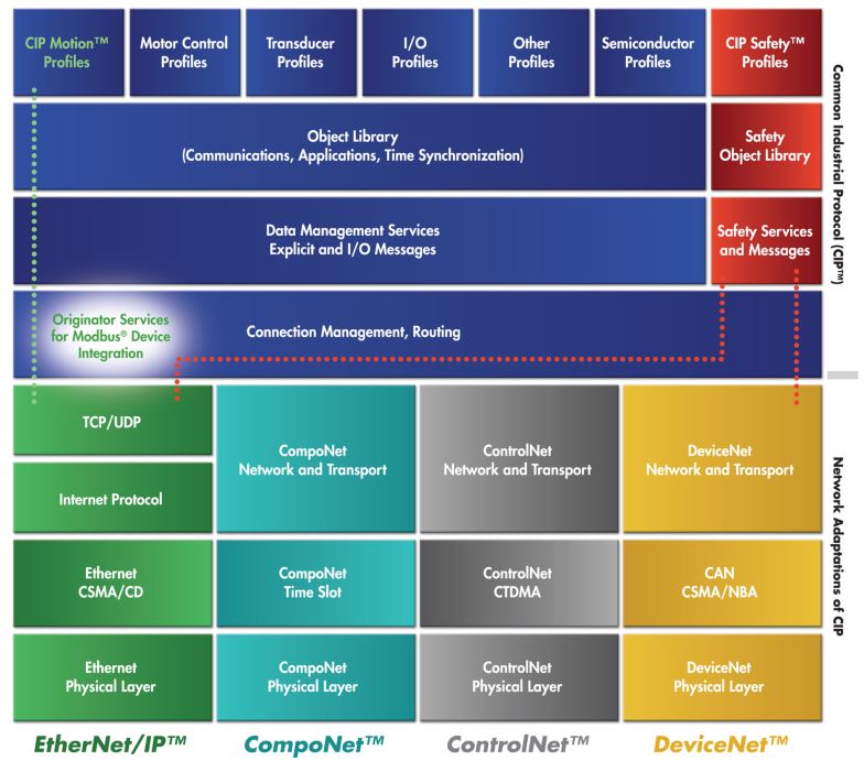
Below the profiles sits the Object Library, which contains all standardized communication, application, timing, safety, and synchronization objects. This is followed by data management services, which include:
- Explicit messaging for configuration and diagnostics
- Implicit (I/O) messaging for real-time control
Under these layers, connection management and routing define how devices establish communication paths, set update rates, exchange cyclic data, and send messages across multiple CIP networks.
At the bottom of the architecture are the network adaptation layers, which describe how CIP maps onto different physical networks:
- EtherNet/IP → Ethernet, TCP/UDP, IP (defined in CIP Networks Library Volume 2)
- CompoNet → High-speed time-slot mechanism (Volume 6)
- ControlNet → Deterministic CTDMA (Volume 4)
- DeviceNet → CAN-based messaging (Volume 3)
This design allows the same CIP application layer to run uniformly across four very different network technologies, ensuring interoperability and scalability throughout industrial systems.
2.2 The CIP Object Model
The CIP protocol is built around a standard object model. Every CIP device exposes its internal features through a structured set of objects, allowing PLCs, drives, tools, robots, and sensors to interact with them in a predictable and uniform way.
Read more: For a complete walkthrough of classes, instances, attributes, services, and how the object model works in practice, see our CIP Object Model Explained: Classes, Instances, Attributes, and Services article.
2.2.1 Objects, Classes, Instances, and Attributes
Every CIP object contains four key elements:
- Class — defines the type of object (e.g., Identity, Assembly, Connection Manager)
- Instances — individual occurrences of that class
- Attributes — data values stored in the object
- Services — actions that can be performed on the object
This structure applies consistently across all CIP devices, regardless of device type or manufacturer.
2.2.2 What Objects Represent
Objects are used to represent almost everything inside a CIP device, including:
- Identity information (vendor ID, product type, revision, serial number)
- I/O data (input assemblies, output assemblies)
- Device parameters (configuration settings, operating modes)
- Network interfaces (Ethernet link, TCP/IP interface, DeviceNet interface)
- Connections (I/O connections, explicit messaging connections)
- Motion axes (feedback, command, synchronization objects)
- Safety channels (safe inputs, safe outputs, validator/supervisor objects)
2.2.3 Object Addressing
The CIP addressing structure is simple and universal:
Class → Instance → AttributeExample:
Class 0x01 → Instance 1 → Attribute 4Reading this triple from any CIP device returns the device revision. The same addressing works on EtherNet/IP, DeviceNet, ControlNet, and CompoNet — only the transport changes.
2.2.4 Key CIP Object Class IDs
The CIP Networks Library Volume 1 defines hundreds of standard object classes. The most commonly encountered ones:
| Class ID | Hex | Object | Purpose |
|---|---|---|---|
| 1 | 0x01 | Identity | Vendor, product, revision, serial number — required on every CIP device |
| 2 | 0x02 | Message Router | Routes CIP messages to internal objects |
| 4 | 0x04 | Assembly | Bundles I/O data for cyclic exchange |
| 5 | 0x05 | Connection | Represents an established CIP connection |
| 6 | 0x06 | Connection Manager | Opens, closes, monitors CIP connections |
| 15 | 0x0F | Parameter | Configuration parameters |
| 71 | 0x47 | Device Level Ring (DLR) | Ring redundancy on EtherNet/IP |
| 78 | 0x4E | Ring Supervisor | DLR supervisor function |
| 245 | 0xF5 | TCP/IP Interface | IP configuration |
| 246 | 0xF6 | Ethernet Link | Port status, MAC, error counters |
Class IDs 0x00–0x63 are reserved for ODVA-defined common objects. 0x64–0xC7 are vendor-specific. 0xC8 and above are reserved.
3. CIP Services
Services define what actions can be performed on objects. Services are identified by a service code in every CIP request and reply.
3.1 Common Services
The CIP Common specification (Volume 1, Appendix A) defines a standard set of services that work on most object classes:
| Service Code | Service | Purpose |
|---|---|---|
| 0x01 | Get_Attributes_All | Read every attribute of an instance in one transaction |
| 0x02 | Set_Attributes_All | Write all attributes |
| 0x05 | Reset | Reset the object or device |
| 0x06 | Start | Start the object’s behavior |
| 0x07 | Stop | Stop the object’s behavior |
| 0x0E | Get_Attribute_Single | Read one specific attribute |
| 0x10 | Set_Attribute_Single | Write one specific attribute |
| 0x54 | Forward_Open | Establish a CIP connection — the most important service for I/O |
| 0x4E | Forward_Close | Close a CIP connection |
| 0x52 | Unconnected_Send | Send a message that does not require a pre-established connection |
Class-specific and instance-specific services extend this base set. The Assembly Object adds Get_Member and Set_Member. The Connection Manager defines Forward_Open and Forward_Close. The Identity Object adds Reset. Each object class in Volume 1 Chapter 5 documents which services apply.
A complete CIP request consists of: service code + class/instance/attribute path + optional data. That is it. Compact and consistent.
4. Messaging in the CIP Protocol
CIP communications fall into two major categories: explicit messaging and implicit messaging.
4.1 Explicit Messaging
Explicit messaging is used for:
- Configuration
- Diagnostics
- Parameter access
- Device management
- Status checks
- Programmatic queries
Characteristics:
- Request/response format
- Each message includes the full object path and service code
- Not time-critical
- Typically uses TCP/IP (in EtherNet/IP systems)
Example: “Read attribute 2 from instance 1 of class 0x01.”
4.2 Implicit Messaging (I/O Messaging)
Implicit messaging is used for real-time data such as:
- Sensor values
- Drive commands
- Motion feedback
- Safety signals
- High-speed I/O updates
Characteristics:
- No embedded service codes
- Uses connection IDs instead of explicit addressing
- Very efficient — compact packets
- Can be multicast (one producer, many consumers)
- Often uses UDP (in EtherNet/IP systems, on port 2222)
Implicit messaging is the backbone of real-time industrial control using the CIP protocol.
4.3 UCMM — Unconnected Message Manager
The Unconnected Message Manager (UCMM) handles explicit messages that do not require a pre-established connection. UCMM is how a configuration tool, HMI, or PLC can send a one-shot request to any CIP device without first opening a Forward_Open connection. UCMM is essential for device discovery, parameter access, and any traffic that does not justify the overhead of a dedicated connection.
5. CIP Connections and the Connection Manager
CIP is a connection-based protocol. Before exchanging real-time I/O, devices establish a connection using the Forward_Open service handled by the Connection Manager Object (class 0x06).
5.1 What a CIP Connection Defines
A CIP connection specifies:
- Direction — producer to consumer (and optionally consumer to producer)
- Connection trigger — cyclic, change-of-state, application object triggered
- Update rate (RPI — Requested Packet Interval) — typically 1–100 ms
- Timeout multiplier — how long without packets before the connection is declared dead
- Unicast or multicast behavior
- Message size — input and output data sizes
- Application path — which Assembly objects (or other objects) carry the data
- Connection priority — Scheduled, High, Low, Urgent
5.2 Connection Transport Classes
CIP defines several transport classes with different reliability and acknowledgment behaviors:
- Class 0 — Unidirectional, no acknowledgments, used for cyclic I/O production
- Class 1 — Bidirectional with implicit sequence-number tracking, the most common class for I/O
- Class 2 — Bidirectional with explicit acknowledgments, used for connected explicit messaging
- Class 3 — Bidirectional with sequenced acknowledgments, used for explicit messaging requiring strict ordering
Class 1 is what carries the cyclic I/O between PLCs and remote I/O blocks on EtherNet/IP. Class 3 is what carries connected explicit messaging when an application opens a long-lived configuration session.
5.3 Types of CIP Connections
- I/O Connections — implicit messaging, used for real-time I/O exchange
- Explicit Messaging Connections — explicit requests/responses over an established connection (more efficient than UCMM for repeated configuration access)
Multiple CIP connections may be active at once, each with its own independent timing and data mapping.
6. The Producer/Consumer Model
The CIP protocol uses a producer/consumer architecture instead of traditional source/destination addressing.
Benefits include:
- More efficient bandwidth use — one multicast packet feeds many consumers
- Lower network traffic — no redundant copies of the same data
- Decoupled architecture — producers do not need to know how many consumers exist
- Lower latency for real-time control
Example: a single drive can produce a speed feedback multicast packet, and multiple controllers can consume it simultaneously. The drive does not maintain a list of subscribers; it simply publishes to a multicast group, and any device that has subscribed (through Forward_Open) receives the data.
This model scales naturally for distributed automation and is one of the reasons EtherNet/IP, DeviceNet, ControlNet, and other CIP-based networks scale so effectively.
7. CIP Networks (Physical Transport Layers)
The CIP protocol itself is media independent, meaning the same application-level protocol can run over different physical network layers. The four official CIP networks are EtherNet/IP, DeviceNet, ControlNet, and CompoNet.
7.1 EtherNet/IP
EtherNet/IP adapts the CIP protocol to standard Ethernet technologies (defined in CIP Networks Library Volume 2).
It uses:
- TCP/IP for explicit messaging on port 44818
- UDP/IP for implicit messaging on port 2222
- Standard IEEE 802.3 Ethernet physical layers
EtherNet/IP supports:
- Star, ring, and linear topologies
- Device Level Ring (DLR) for sub-3 ms recovery
- High-speed multicast I/O
- Motion control via CIP Motion
- Safety control via CIP Safety
- Time synchronization via CIP Sync
It is today one of the world’s most widely deployed industrial Ethernet protocols because it is simple, scalable, and supports both real-time I/O and enterprise connectivity.
7.2 DeviceNet
DeviceNet adapts the CIP protocol to the CAN bus (Volume 3 of the CIP Networks Library), offering:
- Low installation cost
- Built-in device power (24 VDC on the same cable)
- Short deterministic update cycles
- Trunk-line / drop-line wiring
DeviceNet is ideal for:
- Proximity sensors
- Simple valves
- Light stacks
- Simple I/O devices
- Small networked machine modules
It remains widely deployed in compact machines and industrial subsystems where the cost and complexity of Ethernet are not justified.
7.3 ControlNet
ControlNet adapts CIP for high-speed, deterministic control using TDMA scheduling (CTDMA, Concurrent Time Domain Multiple Access). Defined in Volume 4 of the CIP Networks Library.
It provides:
- Predictable update times
- High-speed communication
- Redundant network options
- Coordinated control across multiple devices
ControlNet is now being phased out in favor of EtherNet/IP for new installations, but is still found in many legacy and process-industry deployments.
7.4 CompoNet
CompoNet (Volume 6) is optimized for:
- Very small data packets
- Very fast update rates
- Large numbers of tiny I/O devices
Typical applications: packaging machines, small pick-and-place systems, assembly line devices. CompoNet uses a single-pair wire with fixed time-slot allocation for deterministic I/O.
8. CIP Object Library and Device Profiles
The CIP protocol defines a large library of standard objects that represent general functions, application functions, and network-level functions. CIP Networks Library Volume 1, Chapter 5 documents every standard object in detail.
General Objects
- Identity Object (0x01)
- Message Router (0x02)
- Assembly Object (0x04)
- Connection Object (0x05)
- Connection Manager (0x06)
- Parameter Object (0x0F)
- Parameter Group Object (0x10)
- Acknowledge Handler (0x2B)
- File Object (0x37)
Application Objects
- Analog Input / Output Point and Group objects
- Discrete Input / Output Point and Group objects
- Presence Sensing
- Motor Data
- Motion Axis
- Event Log
- Power and Energy Management
- Safety-related objects (Safety Supervisor, Safety Validator, etc.)
Network Objects
- Ethernet Link (0xF6)
- TCP/IP Interface (0xF5)
- DeviceNet Interface
- ControlNet Interface
- Redundancy objects
- QoS and SNMP objects
- DLR Object (0x47)
- Ring Supervisor (0x4E)
Device Profiles
Device profiles standardize how entire classes of devices behave. CIP Networks Library Volume 1, Chapter 6 defines profiles for:
- AC drives
- DC drives
- Motion drives (servo)
- Encoders
- PLCs (Programmable Controllers)
- HMIs (Human-Machine Interfaces)
- Vacuum controllers
- Safety I/O devices
- Motor overloads
- Contactors
- Proximity sensors
- Photoelectric sensors
- Limit switches
- Pneumatic valves
- Communications adapters
- And many more
Each profile specifies:
- Required objects
- Optional objects
- Standard I/O assemblies (so a generic AC Drive Profile 0x02 device exposes the same speed reference and feedback assemblies regardless of vendor)
- Device behavior rules
- Required services
Profiles ensure interoperability between devices from different manufacturers. In theory, swapping one AC Drive Profile 0x02 device for another should not require PLC code changes. In practice, vendor-specific extensions often live alongside the standard profile, so portability is partial but real.
9. Assembly Objects and I/O Mapping
The Assembly Object (class 0x04) is one of the most important in the CIP protocol. It allows:
- Grouping data from multiple objects
- Creating input and output data blocks
- Defining configuration blocks
- Allowing cyclic I/O updates with one transaction
Types of Assemblies
- Input assembly → data produced by the device (read by the PLC)
- Output assembly → data consumed by the device (written by the PLC)
- Configuration assembly → data used to configure the device at connection establishment
How Assemblies Work in Practice
When a PLC opens a Forward_Open connection to a remote I/O block, the request specifies:
- The Connection Path pointing to the input assembly instance
- The Connection Path pointing to the output assembly instance
- (Optionally) the Connection Path to a configuration assembly
The remote I/O block then exchanges those assemblies cyclically with the PLC at the agreed RPI. Each cycle is one packet in each direction containing the entire assembly — no per-attribute addressing overhead. This is why CIP can deliver hundreds or thousands of I/O updates per second on moderate hardware.
Assembly objects make I/O communication efficient by consolidating data into predictable formats.
10. Electronic Data Sheets (EDS Files)
An Electronic Data Sheet (EDS) is a simple text file that describes a CIP device’s capabilities to configuration tools. CIP Networks Library Volume 1, Chapter 7 defines the EDS format in detail.
An EDS file describes:
- Device identity (Vendor ID, Product Code, Device Type)
- I/O assemblies (input, output, configuration)
- Communication options
- Parameters with display formatting, scaling, and units
- Grouping for tool UI
- Supported connections
- Capability flags
- Electronic keying requirements
EDS files allow configuration tools to:
- Discover device capabilities without manual lookup
- Display parameters meaningfully (units, ranges, descriptions)
- Download configuration to devices
- Validate assemblies before opening connections
- Configure devices offline
EDS files eliminate the need for bulky Parameter Objects in many small devices and make multi-vendor integration possible. When you import a third-party drive’s EDS into Studio 5000 or another CIP configuration tool, the tool instantly knows how to talk to that device.
11. CIP Routing Across Multiple Networks
One of the CIP protocol’s most powerful features is seamless routing between different CIP network types. CIP Networks Library Volume 1, Chapter 10 defines the routing model.
A device on EtherNet/IP can communicate with a device on DeviceNet or ControlNet by passing through a CIP-aware router using path segments that describe the full route. The path includes:
- The egress port from each router (Port Segment)
- The address on the next network (Logical Segment)
- The final object reference on the destination device
Routing is performed using:
- Unconnected_Send for explicit messaging across networks
- Forward_Open for connected messaging across networks (the connection itself spans the routers)
Routers dynamically examine the path segments and forward messages accordingly — no manual pre-configuration of routing tables is required. The originator specifies the entire route; intermediate routers simply follow the breadcrumbs.
This is what lets a ControlLogix PLC on EtherNet/IP read data from a DeviceNet sensor through a CIP-capable scanner module, all using the same protocol semantics.
12. CIP Data Management and Data Types
CIP supports standardized IEC 61131-3-aligned data types (CIP Networks Library Volume 1, Appendix C), including:
Elementary Data Types
- BOOL — 1-bit boolean
- SINT, INT, DINT, LINT — 8/16/32/64-bit signed integers
- USINT, UINT, UDINT, ULINT — 8/16/32/64-bit unsigned integers
- BYTE, WORD, DWORD, LWORD — 8/16/32/64-bit bit strings
- REAL — 32-bit IEEE 754 floating point
- LREAL — 64-bit IEEE 754 floating point
- STRING, SHORT_STRING, STRING2, STRINGN, STRINGI — Various string representations
- DATE, TIME_OF_DAY, DATE_AND_TIME, TIME — Time and date types
- EPATH — Encoded CIP path
- ENGUNIT — Engineering unit identifier
Structured Types
- STRUCT — Composite of multiple members
- ARRAY — Fixed-size sequence of one type
- ABBREV_STRUCT — Compact struct without member tags
Data structures can include arrays, composite structures, and symbolic path references. Logical segments provide flexible addressing for objects, instances, attributes, and member data. Path segments allow CIP to express complex object hierarchies and routing paths in a compact binary format.
13. CIP Status Codes and Error Handling
When a CIP service fails, the response carries a General Status Code and optionally an Extended Status Code that explains the failure. CIP Networks Library Volume 1, Appendix B defines these codes.
Common General Status Codes
| Code | Meaning |
|---|---|
| 0x00 | Success |
| 0x01 | Connection failure |
| 0x02 | Resource unavailable |
| 0x03 | Invalid parameter value |
| 0x04 | Path segment error |
| 0x05 | Path destination unknown |
| 0x06 | Partial transfer |
| 0x08 | Service not supported |
| 0x09 | Invalid attribute value |
| 0x0E | Attribute not settable |
| 0x0F | Privilege violation |
| 0x10 | Device state conflict |
| 0x11 | Reply data too large |
| 0x13 | Not enough data |
| 0x14 | Attribute not supported |
| 0x15 | Too much data |
| 0x16 | Object does not exist |
| 0x20 | Invalid parameter |
Extended Status Codes provide more specific reason information — for example, a Forward_Open that returns General Status 0x01 (Connection failure) might include an Extended Status indicating which specific Connection Manager check failed (out of connections, RPI not supported, ownership conflict, etc.).
14. CIP Safety
CIP Safety extends the CIP protocol to support functional safety up to SIL3, Cat 4, and PL e levels. Defined in CIP Networks Library Volume 5.
Features:
- Safety and standard data on the same network
- Black Channel communication model (the standard network is untrusted; the safety layer validates each message independently)
- Error detection (Safety CRC, time stamps, sequence numbers, Time Coordination Messages, complement data)
- Safety Supervisor and Safety Validator objects
- Safe state handling
- SafetyOpen (instead of Forward_Open) for connection establishment
- SNN (Safety Network Number), SCID (Safety Configuration Identifier), and CFUNID for identification
Typical CIP Safety devices:
- Safety PLCs (GuardLogix and similar)
- Safety relays and contactors
- Emergency stop units
- Light curtains
- Safety interlock switches
- Safety analog sensors
- Dual-channel safety I/O blocks
- Safety-rated drives with STO/SS1/SS2
CIP Safety is widely used in modern machinery because it reduces wiring, improves flexibility, and integrates seamlessly with standard control systems.
15. CIP Sync and CIP Motion
The CIP protocol includes advanced extensions for real-time synchronization and motion control.
15.1 CIP Sync
CIP Sync uses IEEE 1588 Precision Time Protocol (PTP) to synchronize devices to within sub-microsecond accuracy. This gives all devices a shared notion of time, enabling coordinated and deterministic control functions.
CIP Sync is foundational for CIP Motion and for time-stamping of high-resolution data acquisition.
15.2 CIP Motion
CIP Motion builds on CIP Sync and provides:
- Multi-axis coordination
- High-speed motion updates (sub-millisecond cycle times)
- Accurate drive-to-drive synchronization
- Integrated motion and standard I/O on the same network
- Support for complex motion profiles (interpolation, gearing, camming)
- Cyclic exchange of position, velocity, torque setpoints and feedback
Typical applications:
- Robotics
- Packaging machinery
- Servo-axis coordination
- High-speed assembly systems
- Multi-axis machine tools
CIP Motion allows a single EtherNet/IP network to handle both standard control and advanced motion control, simplifying machine design. It is Rockwell’s primary motion network strategy and is supported by Kinetix drives, ControlLogix and CompactLogix safety/motion controllers.
16. CIP Security
CIP Security is an optional extension that adds authentication, integrity, and confidentiality to CIP messages. Published by ODVA starting in 2015.
Features:
- Device authentication via X.509 certificates
- Message integrity via HMAC
- Confidentiality via TLS (for explicit messaging) and DTLS (for implicit messaging)
- Access control policies per object class or service
Adoption has been slower than the specification deserves. Most CIP devices in the field still communicate without authentication or encryption. For practical security posture, treat CIP networks as untrusted by default and apply network segmentation according to IEC 62443.
17. Real-World Example: A PLC Communicating with a CIP Device
Imagine a PLC interacting with a smart I/O block or a servo drive using the CIP protocol.
Step 1 — Forward_Open
The PLC sends a Forward_Open request to the device’s Connection Manager (class 0x06) specifying:
- Input assembly instance (e.g., assembly instance 101)
- Output assembly instance (e.g., assembly instance 100)
- Configuration assembly instance (e.g., assembly instance 102)
- RPI (update rate, e.g., 10 ms)
- Trigger method (cyclic, change-of-state, application object)
- Timeout settings (multiplier of RPI)
- Connection priority and transport class
- Network connection parameters (size, type)
Step 2 — Connection Established
The device’s Connection Manager validates the request, allocates resources, and returns a Forward_Open reply with a Connection ID. The device prepares data structures for cyclic exchange.
Step 3 — Implicit Messaging Starts
At each RPI (e.g., every 10 ms), the device:
- Produces input data (the contents of input assembly 101)
- Consumes output data (the contents of output assembly 100)
The PLC updates its internal I/O tables accordingly. On EtherNet/IP this happens via UDP packets to port 2222 carrying the Connection ID assigned in Forward_Open.
Step 4 — Runtime Behavior
The PLC logic processes the data in real time:
- Inputs → used for control decisions
- Outputs → sent to actuators or drives
If a cycle is missed (no packet received within the timeout), the connection is declared dead and the device drops to a safe or default state.
Step 5 — Forward_Close
When the system no longer requires the connection, the PLC issues Forward_Close to the device’s Connection Manager. The device deallocates resources, and the cyclic exchange stops.
This same Forward_Open → cyclic exchange → Forward_Close pattern applies to every CIP I/O connection across every CIP network type.
18. Benefits of the CIP Protocol
Interoperability. Vendors follow common object models and profiles.
Scalability. Works for small sensors and large distributed systems.
Real-time performance. Implicit messaging and multicast enable extremely fast I/O.
Vendor-neutral architecture. Standardized objects and services ensure predictable behavior across manufacturers.
Rich feature set. Safety, motion, time sync, energy management, configuration, diagnostics — all defined within the same protocol family.
Multi-network operation. The same application protocol runs on four different industrial network types.
Seamless routing. CIP-routing lets messages travel across different networks without special configuration.
Mature ecosystem. Hundreds of certified vendors, well-developed engineering tools (Studio 5000, RSLinx), and decades of field deployment.
19. CIP vs Other Industrial Protocols
CIP vs PROFINET
| Feature | CIP Protocol | PROFINET |
|---|---|---|
| Object model | Strong | Moderate |
| Safety | CIP Safety | PROFIsafe |
| Motion | CIP Motion | PROFINET IRT |
| Network independence | Yes (4 networks) | No (Ethernet only) |
| Multicast efficiency | High | Moderate |
| Primary ecosystem | Rockwell-centric | Siemens-centric |
CIP vs EtherCAT
| Feature | CIP Protocol | EtherCAT |
|---|---|---|
| Cycle time | Sub-millisecond achievable | Tens of microseconds achievable |
| Architecture | Programmable, flexible, object-oriented | Hard real-time, in-flight processing |
| Object model | Full CIP model | Limited (CoE dictionary on top) |
| Motion | CIP Motion | Native via SoE / CoE |
| Topology | Star, ring (DLR), linear | Daisy-chain, ring |
CIP is generally more flexible and IT-friendly, while EtherCAT excels in raw determinism and motion synchronization.
CIP vs Modbus TCP
Modbus TCP is simpler, register-based, and widely supported by inexpensive devices. CIP is object-based, far richer, and supports advanced features like Safety, Motion, and routing that Modbus does not.
For comparison: Modbus reads holding register 40001 with a 7-byte request. CIP reads Class 0x01 Instance 1 Attribute 4 with a similar-length request — but the same client can also Forward_Open a cyclic connection, route across networks, and access hundreds of standard object classes.
20. The Future of the CIP Protocol
CIP development continues to evolve with:
- Industry 4.0 and Industrial IoT integration
- Cloud connectivity via OPC UA bridging and direct cloud-aware devices
- TSN (Time-Sensitive Networking) support — EtherNet/IP-over-TSN is in active development
- Distributed analytics and edge computing patterns
- Network redundancy improvements beyond DLR
- Advanced cybersecurity via wider CIP Security adoption
- Energy management through CIP Energy device profiles
CIP’s modular architecture ensures it remains relevant and adaptable for decades. New extensions can be added without breaking existing devices because the object model is inherently extensible.
Frequently Asked Questions
What does CIP stand for?
CIP stands for Common Industrial Protocol. It is an open, object-oriented application-layer protocol developed by Rockwell Automation and managed by ODVA. It runs over multiple network types including EtherNet/IP, DeviceNet, ControlNet, and CompoNet.
Is CIP the same as EtherNet/IP?
No. CIP is the application-layer protocol — the message format, object model, and services. EtherNet/IP is one of four networks that carry CIP messages over standard Ethernet. CIP also runs on DeviceNet (CAN), ControlNet, and CompoNet. EtherNet/IP is the most common CIP network today.
Is CIP open or proprietary?
CIP is an open standard managed by ODVA. The specification is available to ODVA members. Hundreds of vendors implement CIP devices. The protocol itself is vendor-neutral, although Rockwell Automation is its largest implementer and many vendor-specific extensions exist on top of the standard.
What ports does CIP use over EtherNet/IP?
CIP over EtherNet/IP uses TCP port 44818 for connection-oriented and explicit messaging, and UDP port 2222 for implicit (cyclic I/O) messaging. Both ports must be reachable for full functionality. UDP port 44818 is also used for ListIdentity device discovery broadcasts.
What is the CIP Object Model?
The CIP Object Model describes every CIP device as a collection of objects. Each object has a Class ID (kind), an Instance ID (which copy), and Attributes (data fields). Services act on objects. The same model works across all CIP networks. See our CIP Object Model Explained article for details.
What is the difference between explicit and implicit messaging?
Explicit messaging is request/response — used for configuration, diagnostics, parameter access. Each message carries the full object path and service code. Implicit messaging is cyclic — used for real-time I/O. It opens a connection once via Forward_Open, then exchanges compact data packets at a fixed interval.
What is Forward_Open?
Forward_Open (service code 0x4B) is the CIP service used to establish a connection for I/O or connected explicit messaging. The originator sends Forward_Open to the target’s Connection Manager Object (class 0x06) specifying the connection parameters. If approved, the target returns a Connection ID and the cyclic exchange begins.
Can CIP run without an Ethernet network?
Yes. CIP runs on DeviceNet (CAN bus), ControlNet (coax), and CompoNet (single-pair wire) as well as EtherNet/IP. The application-layer behavior is identical across all four networks — only the transport changes.
What is CIP Safety?
CIP Safety extends CIP to support functional safety up to SIL3, Cat 4, PL e. It adds safety-specific objects (Safety Supervisor, Safety Validator), safety-specific connection establishment (SafetyOpen), and end-to-end validation through Safety CRC, time stamps, and Time Coordination Messages. See our CIP Safety Explained article.
Where can I find the official CIP specification?
The CIP Networks Library is published by ODVA at odva.org. Volume 1 covers the Common Industrial Protocol itself. Volumes 2-7 cover the network adaptations (EtherNet/IP, DeviceNet, ControlNet, CIP Safety, CompoNet, Modbus integration). Access to the full specifications requires ODVA membership.
Conclusion
The CIP protocol is one of the most comprehensive and powerful communication frameworks in industrial automation today. Its object-based architecture, rich set of services, predictable behavior, and ability to run on multiple network types make it ideal for modern manufacturing systems.
Whether you are working with PLCs, robots, drives, safety systems, sensors, motion control, or energy management devices, understanding the CIP protocol gives you a clear advantage in designing, troubleshooting, and optimizing industrial automation systems. This pillar guide will be updated as the specifications evolve and new sub-articles are published. Bookmark it as your CIP reference.