
High-Availability Seamless Redundancy, or HSR, is one of the most advanced real-time redundancy mechanisms in industrial communication. It is mostly used in IEC 61850 digital substations, protection and control systems, and process bus networks where communication cannot stop even for a fraction of a second. HSR ensures zero-time recovery, meaning communication continues without interruption even during link or node failures. This property makes it essential for applications handling Sampled Values, GOOSE messaging, and any traffic requiring deterministic delivery.
Unlike traditional redundancy methods that wait for topology change detection, HSR operates with frame-level duplication and continuous forwarding. Every transmitted Ethernet frame is duplicated and sent in two directions around a ring. Every node forwards and filters frames as they move around the network. Because both paths are active simultaneously, a failure does not require any switchover; the communication pattern is already redundant. This architecture enables true seamlessness.
This article explains HSR in deep technical detail while maintaining a clear and readable structure. It is designed for protection engineers, SCADA specialists, OT network architects, and automation engineers who require precise understanding of HSR internals.
Table of Contents
HSR Fundamentals and the Motivation Behind It
In critical industrial systems, a communication interruption—even for a few milliseconds—can cause protection misoperations, automation failures, or loss of measurement data. In IEC 61850 process bus networks, Sampled Values often arrive at thousands of packets per second and must be processed continuously. Any gap can trigger alarms or disrupt protection logic. Traditional redundancy mechanisms such as RSTP, MRP, or vendor ring protocols provide fast recovery but not seamless recovery. They require time to recalculate topology, block ports, or redirect paths.
HSR eliminates this need for recovery. It works on the principle of parallel frame delivery. Each device sends two copies of every frame—one clockwise and one counterclockwise—around a ring of participating devices. Any device that needs to receive a frame gets two opportunities to receive it, and the duplicate arriving second is discarded. A failure in any link simply removes that direction, but the opposite direction continues uninterrupted.
This zero-time behavior is the core purpose of HSR. It is particularly valuable in IEC 61850 digital substations where protection IEDs must exchange trip signals and continuous measurements, or in industrial systems where real-time reliability is non-negotiable.
Network Architecture and Node Types in HSR
An High-Availability Seamless Redundancy network consists of a ring of specialized devices called DANH (Doubly Attached Node using HSR). Each DANH has two ports that connect into the ring. The device contains a forwarding engine that handles incoming and outgoing frames according to the HSR rules.
Nodes in an HSR ring perform three key roles simultaneously:
- Originator: Devices send application frames through the ring. The device duplicates each frame and transmits copies on both ports.
- Receiver: Devices consume frames addressed to them or multicast frames relevant to their functions.
- Forwarder: Devices forward frames arriving on one port to the opposite port unless they are duplicates.
This forwarding responsibility distinguishes HSR from PRP and traditional Ethernet. In HSR, every node behaves like a small cut-through switch, enabling continuous flow around the ring.
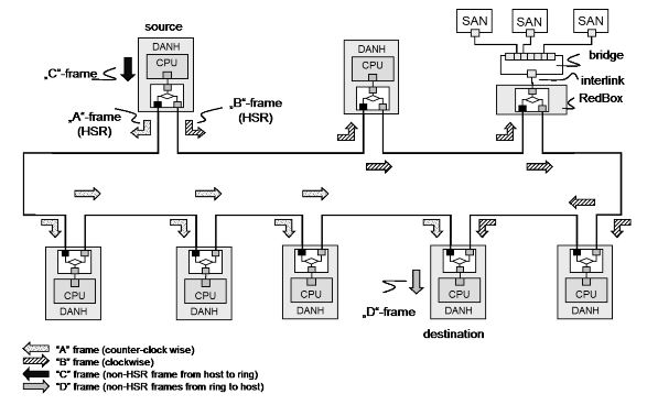
This diagram shows how frames travel inside an HSR ring. The source DANH sends two HSR frames at the same time: one moving clockwise and the other counter-clockwise. Each DANH in the ring forwards the frames through its opposite port while checking sequence numbers to remove duplicates.
A SAN (Singly Attached Node) sends normal Ethernet frames into the ring through a RedBox. The RedBox converts these frames into HSR frames before injecting them. When frames leave the ring toward a SAN, the RedBox removes the HSR header and delivers a single non-HSR frame to the SAN.
The destination DANH receives both copies of each HSR frame, processes the one that arrives first, and discards the duplicate. This illustrates the essential behavior of HSR: two active paths, continuous forwarding, and seamless operation even if one direction fails.
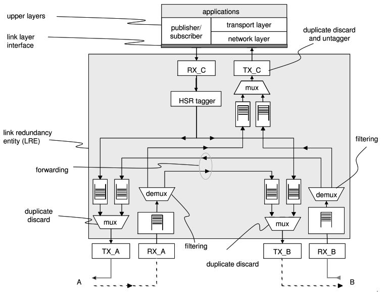
Link Redundancy Entity (LRE) — The Core of HSR Behavior
Within each DANH is a component called the Link Redundancy Entity. The LRE:
- Duplicates outgoing frames.
- Inserts the HSR tag.
- Assigns sequence numbers.
- Performs duplicate detection.
- Forwards frames from one port to the other.
- Maintains per-node sequence tables.
Every transmitted frame receives a unique sequence number from the LRE. Each device keeps a table with the most recent sequence numbers received from every other device. If a frame arrives with a sequence number already recorded, it is discarded as a duplicate.
This duplicate filtering is essential to prevent endless loops around the ring.
HSR Frame Format and Tagging Mechanism
An HSR frame carries an additional header inserted between the Ethernet header and payload. The HSR header contains:
- The Ethertype (HSR_EtherType = 0x892F)
- The sequence number (SeqNr)
- The frame size (LSDUsize)
- The Path ID to indicate the sending port (A=0, B=1)
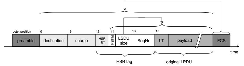
This header allows every node to understand whether it has seen the frame before, whether the frame has completed a loop, and whether it originates from the opposite side of the ring.
Regular Ethernet switches do not understand or forward HSR frames correctly. Therefore, HSR rings must be composed entirely of HSR-aware devices or interconnected via RedBoxes or QuadBoxes as defined later.
Forwarding, Filtering, and Cut-Through Behavior
When a DANH receives a frame on Port A, it performs several operations:
- Checks the HSR tag to identify the source and sequence number.
- Determines whether the frame is new or duplicate.
- If the frame is new, passes it up to the application if relevant.
- Forwards the frame to Port B.
The device performs the same process in the opposite direction.
Forwarding is implemented in cut-through mode. This minimizes latency because the node does not wait for the full frame before forwarding. Instead, it begins forwarding as soon as the destination MAC address and HSR tag are processed. This forwarding delay is typically only a few microseconds.
As a result, even a ring with many devices still maintains predictable latency, although ring size must be limited in practice for performance reasons.
Eliminating Circulating Frames
Frames circulate around the ring in both directions. Without a mechanism to stop them, frames would complete loops indefinitely. HSR devices use the following rules to remove circulating frames:
- A node discards the frame if it arrives from the opposite direction after the node has already forwarded it.
- A node discards a frame if the sequence number matches an entry in its table.
- A node discards a frame that returns to the originator.
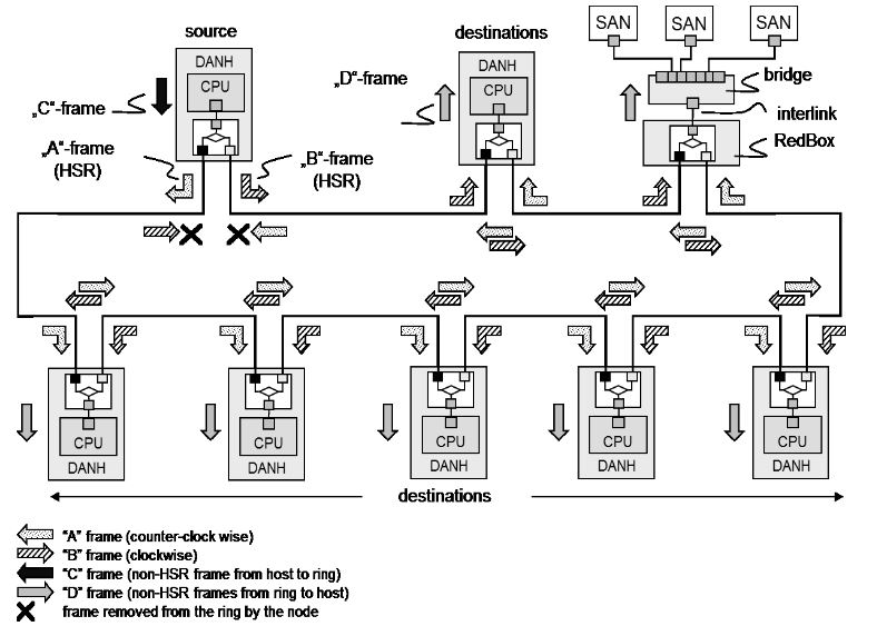
This ensures that each frame completes exactly one round trip before being removed.
Supervision Frames and Node Awareness
High-Availability Seamless Redundancy provides built-in supervision. Each DANH periodically sends supervision frames that allow the other nodes to maintain a NodeTable. This table records:
- Device MAC addresses
- Last sequence numbers received
- Ring direction reachability
- Timeout and validity status
Supervision frames allow the system to detect missing nodes or broken paths even if application traffic is light. This awareness helps operators detect network problems before they become critical.
RedBoxes — Integrating Non-HSR Devices and PRP Devices
A RedBox is a gateway device that connects non-HSR equipment to an HSR ring. A RedBox behaves like a DANH toward the ring and like a normal Ethernet switch or PRP device toward legacy equipment.
Its main responsibilities include:
- Converting standard Ethernet frames into HSR frames
- Removing HSR headers for outgoing standard Ethernet frames
- Generating supervision frames for attached devices
- Maintaining sequence number tables
- Ensuring seamless operation across domains
RedBoxes are essential in hybrid PRP–HSR architectures where process bus systems using HSR must interface with station bus networks using PRP.
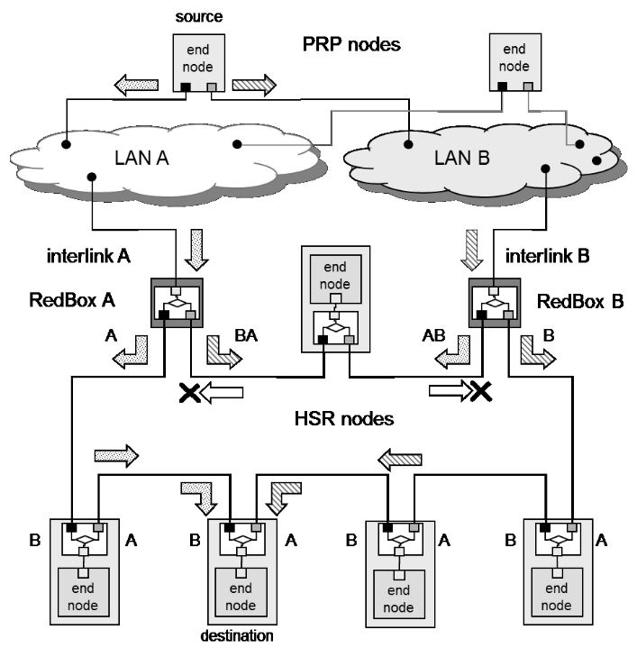
Figure Description — RedBox Integration
Visualize an HSR ring. A RedBox sits at one point, with two ports connected to the ring and one or more ports facing non-HSR devices. The RedBox injects HSR frames into the ring on behalf of these devices.
QuadBoxes — Connecting Multiple HSR Rings
QuadBoxes connect two or more HSR rings together while preserving redundancy. They include at least four HSR ports, forming two or more independent HSR interfaces. QuadBoxes:
- Forward frames from one ring to another
- Prevent duplicates from crossing ring boundaries
- Maintain independent sequence number tables per ring
- Support scalable, multi-ring architectures
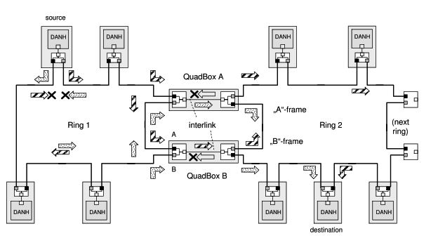
QuadBoxes enable very large networks by dividing them into manageable segments.
HSR Handling of Unicast, Multicast, and Broadcast Frames
HSR handles multicast frames efficiently because all devices must receive them. Frames travel both directions and arrive twice at all nodes. Nodes process the first copy and discard the second.
Unicast frames must also be forwarded all the way around the ring. Even if they are addressed to one specific node, every device along the ring receives them. The destination node consumes the first frame and discards the second. Other nodes merely forward the frames and perform duplicate detection.
Broadcast frames behave like multicast and circulate appropriately.
HSR Performance, Latency, and Ring Size Considerations
Latency in High-Availability Seamless Redundancy networks is predictable but depends on:
- Number of DANH devices in the ring
- Forwarding delay of each device
- Traffic volume, especially Sampled Values
- Medium type (fiber or copper)
- Frame size
Because every frame is duplicated and forwarded by every device, traffic increases with the number of nodes. For this reason, HSR rings are kept relatively small in protection and process bus applications.
Typical practical sizes are:
- 6–12 devices per ring for Sampled Values
- Up to 20–30 devices for general protection and control
- Larger rings only when traffic levels are low
Multiple rings can be connected using QuadBoxes to form large systems without overloading any single ring.
Time Synchronization in High-Availability Seamless Redundancy Networks
Timing traffic, such as IEEE 1588 PTP messages, flows through HSR rings using the same forwarding logic as normal frames. Because each node adds forwarding delay, devices must account for residence time if Transparent Clock behavior is used.
Boundary Clock behavior is often preferred in HSR to regenerate timing at key nodes. PTP traffic must always receive high priority to avoid jitter. Duplicate PTP frames arrive from both directions; the timing module must select the correct path and discard the redundant copy.
Fault Behavior and Zero-Time Recovery
High-Availability Seamless Redundancy excels in fault tolerance. When a link breaks, frames traveling in that direction simply stop. Frames sent in the opposite direction continue to propagate, ensuring uninterrupted delivery. There is no convergence time, no topology recalculation, and no switchover delay.
If a node fails, the ring becomes open at that location, but the other direction remains active. Only adjacency failures at two adjacent points fully break the ring, but even then, local communication within segments can remain active.
This fault-tolerant behavior is essential in protection and process bus networks.
Typical Applications in IEC 61850 Networks
HSR is used in:
- IEC 61850 process bus networks
- Merging unit connections for Sampled Values
- Distributed protection schemes
- Bay-level protection rings
- Industrial automation requiring deterministic Ethernet
Where high-speed, uninterrupted communication is necessary, HSR is an ideal solution.
Engineering Recommendations
Successful HSR design requires attention to:
- Limiting ring size
- Using fiber optic cabling for predictable delays
- Prioritizing critical traffic
- Balancing loads across rings
- Avoiding excessive RedBox connections
- Monitoring supervision frames
- Testing failure scenarios regularly
Hybrid architectures combining HSR and PRP are often preferred in modern digital substations.
Conclusion
High-Availability Seamless Redundancy delivers true seamless redundancy for mission-critical IEC 61850 networks. By duplicating frames and forwarding them through a ring of intelligent nodes, HSR ensures deterministic latency, zero-time recovery, and continuous operation even during network failures. When combined with RedBoxes and QuadBoxes, HSR scales beyond single rings and integrates easily with PRP networks, forming robust hybrid architectures.
For any system requiring uninterrupted, deterministic Ethernet communication—whether in power systems, or industrial automation—HSR remains one of the most reliable and technically elegant redundancy mechanisms available.